Cambridge SoundWorks P500 Subwoofer User Manual
Page 11
11
11
11
jack in the Control Module.
To insure you connect the wires properly (positive to
positive, negative to negative), note which of each
speaker wire’s two conductors is “marked”. This mark-
ing may be a ridge in the insulation, different colored
conductors or printing on only one side. Use the
marked side of the speaker wire to connect the posi-
tive speaker terminals. Use the other wire for the nega-
tive terminals.
Using a small flat bladed screwdriver, loosen the four
set screws inside the Speaker Wire Connector plug.
Pull out the short speaker wires.
Following the markings on the Speaker Wire Connector
diagram (for Right positive, Right negative and so on),
insert the correct wires into the plug’s openings.
RIGHT IN
LEFT IN
CENTER IN
PREAMP LEVEL INPUTS
RIGHT
HIGH PASS
OUT
SUB IN
LEFT
HIGH PASS
OUT
+
–
+
–
+
–
RIGHT
CENTER
LEFT
SPEAKER LEVEL INPUTS
1
2
INTERFA
CE JACKS
ON
AUTO
OFF
12V
AC INPUT
Newton, Massachusetts USA
Made in China
CONTROL MODULE
NO USER SER
VICEABLE P
ARTS INSIDE
REFER SER
VICING T
O QUALIFIED PERSONNEL
00000000
Powered
Subwoofer
POWER
INTERFACE J
ACKS
120VAC
7.0A
Tighten each set screw to hold the wires in place.
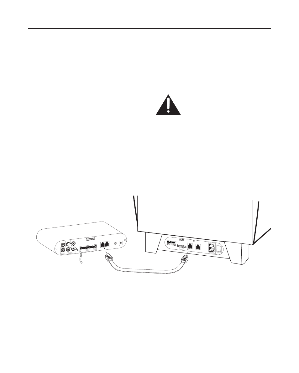
Connect to the Subwoofer Enclosure:
Once the
input connections are made to the Control Module,
connect the Interface Cable from the Control Module
to the Subwoofer Enclosure.
The interface Cable has plugs that look and connect
like telephone connector plugs. The plugs are the
same at both ends.
Making sure both the Control Module and
subwoofer enclosure are disconnected
from any AC power source.
Note:
The second Interface Cable jack on the sub-
woofer enclosure allows you to connect a Newton
Series second subwoofer enclosure with a sub to sub