Speaker level connection, Connect plug to speaker output, Connect plug to control module – Cambridge SoundWorks P500 Subwoofer User Manual
Page 10
10
10
10
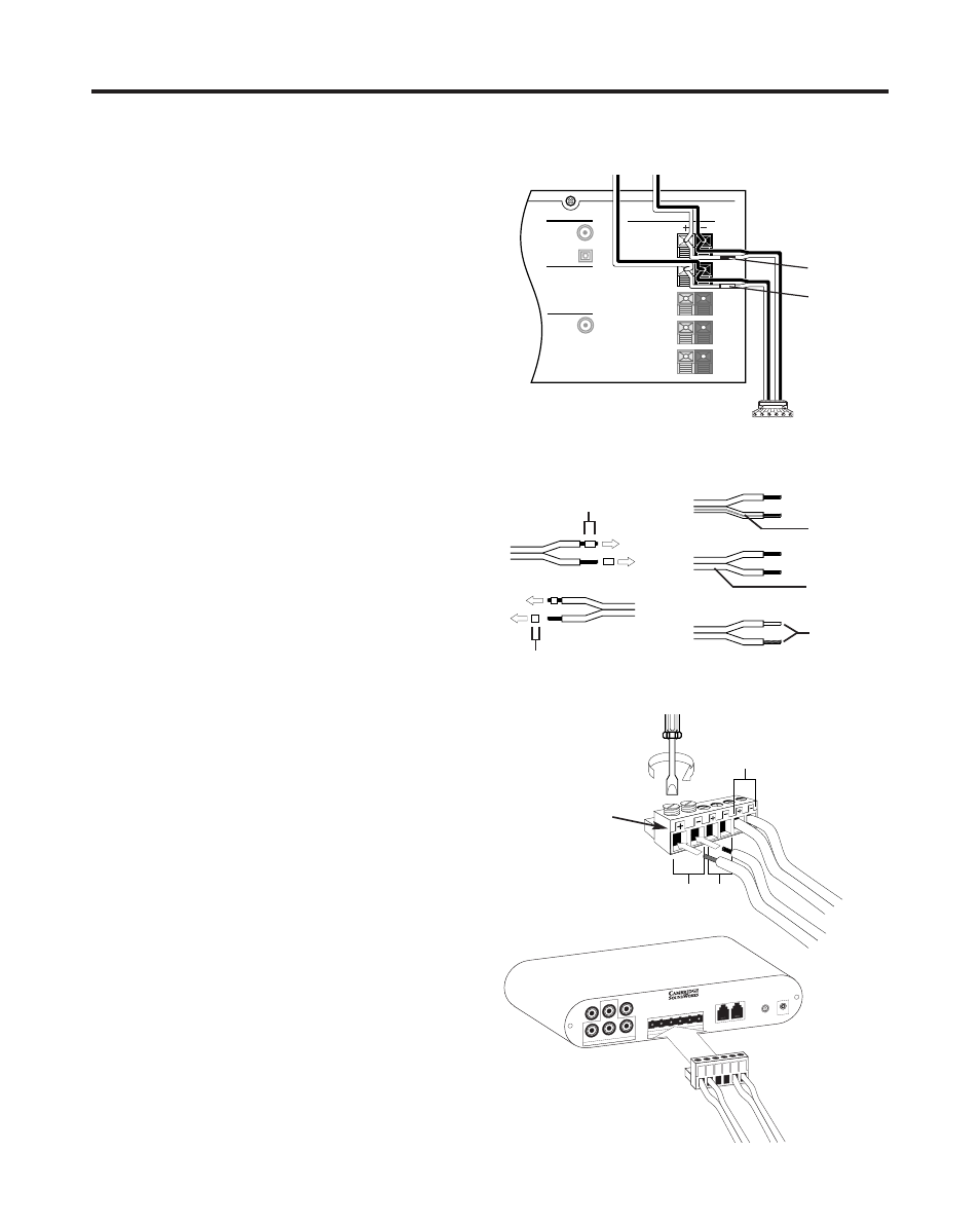
Speaker Level Connection
If your receiver does not have a line-level audio signal
output or if you wish to bypass this output, you need to
connect the speaker level inputs of the Control Module
to your receiver’s speaker outputs.
We provide a Speaker Wire Connector with two short
lengths of speaker wire already connected to it. (If
wires are not long enough to reach from the Control
Module to your power amplifier, you need to attach
longer speaker wires. How to do this is described in
“Attaching longer speaker wires” at the bottom of
this page.)
The speaker wire marked with a red band is Right
postive. The unmarked wire next to it is Right negative.
The Left Positive speaker wire is marked with a white
band. The unmarked speaker wire next to it is
Left negative.
Connect the speaker wires to your receiver’s Left and
Right speaker outputs (Front Left and Front Right
speaker outputs of a multi-channel receiver). You will
have to “parallel connect” theses wires with the main
speaker wires (see diagram). Positive speaker output
terminals will usually be colored red and have a “+”
symbol. Negative speaker output terminals will usually
be colored black and have a “–” symbol.
Finally, insert the Speaker Wire Connector plug into the
COAX
DIGITAL INPUTS
OPTICAL
OUT
SUBWOOFER
MAIN RIGHT
TO FRONT LEFT &
RIGHT SPEAKERS
TO SUB'S
SPEAKER LEVEL
INPUTS
MAIN LEFT
CENTER
REAR RIGHT
REAR RIGHT
SPEAKER OUTPUTS
Red Band
White Band
Connect plug to speaker output
RIGHT
(CENTER)
LEFT
Connect plug to
Control Module
Cambridge SoundWorks Camb
ridge
Sound
Works Cambride
5/8"
3/8"
receiver end
connector end
Prepare Wire
Identify Wire Marking
Ridge on
One Side
Printing on
One Side
Different
Color
Conductors
RIGHT IN
LEFT IN
CENTER IN
PREAMP LEVEL INPUTS
RIGHT
HIGH PASS
OUT
SUB IN
LEFT
HIGH PASS
OUT
+
–
+
–
+
–
RIGHT
CENTER
LEFT
SPEAKER LEVEL INPUTS
1
2
INTERFA
CE JACKS
ON
AUTO
OFF
12V
AC INPUT
Newton, Massachusetts USA
Made in China
CONTROL MODULE
NO USER SER
VICEABLE P
ARTS INSIDE
REFER SER
VICING T
O QUALIFIED PERSONNEL
Attaching longer speaker wires:
First, prepare two
suitable lengths of speaker wire. You can use light-
weight (18-22 gauge) speaker wire because this wire
will not carry any significant electric current. Also, wire
larger than 18 gauge will be somewhat harder to
connect in tandem with another speaker wire.
Strip off 5/8” of insulation from one end of each
speaker wire. Strip of 3/8” of insulation from the other
end. This end connects to the Speaker Wire
Connector Plug.
Wire Connector to Module
Note
Positive (+)
Negative (–)
Sequence