Pn 8248, Pn 8236, Panel mount – Blue Sea Systems 8401 DC 5 Position User Manual
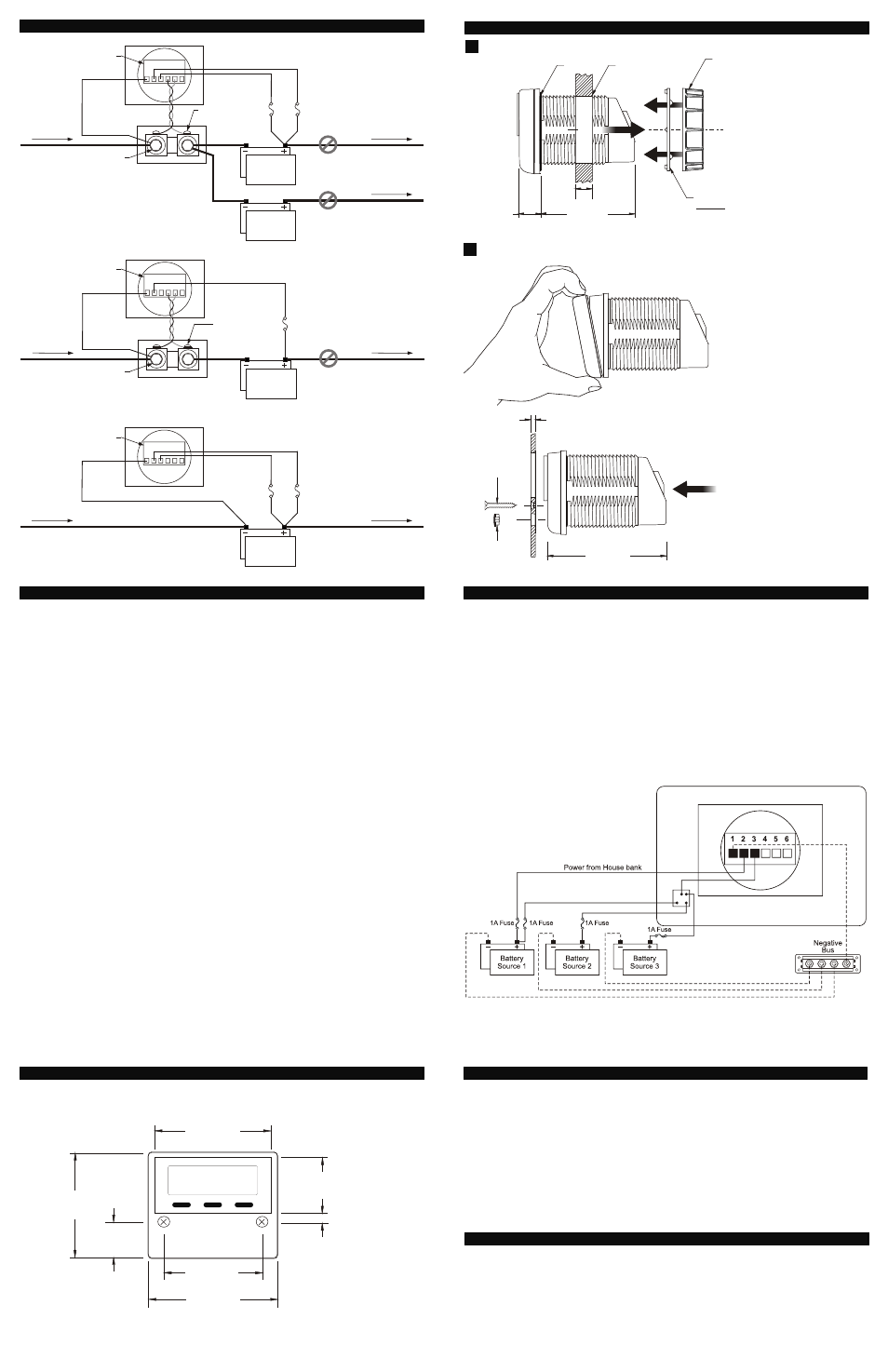
Page 2: Through hole mount, Step 2 step 1
8732 Rev.11
NOTE:
Use16 AWG for all meter wiring.
All models require connections to terminals #1 and #2.
Terminal #3 used for models PN 8235, PN 8248, and PN 8251.
Terminals
#4 and #5 used for PN 8236 and PN 8248 only.
Wire to terminal #1 (Negative)---Supplies the DC negative return from the meter. Make the
connection as close as possible to the DC negative battery terminal to attain the most accurate meter
reading. If installing a current sensing meter, connect to the Load Side of the shunt. The connection to
the shunt must be made under the large bolt, not the small sense screws.
Wire to terminal #2 (Power 8-50V DC Positive)---Supplies power for meter operation. It may be a
different source than the voltage being measured provided the negatives are common. For example,
the meter can be powered from a 12V system and measure the voltage of a 24V battery, if the
negatives of the two batteries are connected together. This wire must be fused as close to the source
as possible (any fuse between 0.5A and 2.0A is acceptable.)
Wire to terminal #3 (Voltage Sensing 0-60V DC Positive)---This wire supplies the voltage to be
measured. Separate voltage sensing is recommended if the source is more than a few feet from the
meter. This helps reduce errors due to voltage drop in the wires to the meter. Make the connection as
close as possible to the DC positive battery terminal to attain the most accurate meter reading. This
wire must be protected by a fuse (any size between 0.5A and 2.0A). If the meter is close to the
measured source, then terminals #2 and #3 may be jumped together and a single wire may be used
for power and voltage sensing.
The wires to terminals #4 and #5 must be a twisted pair to avoid electrical system noise that
will affect the accuracy of current measurement. These may be twisted by hand or by using
an electric drill motor, or twisted pair wire may be purchased from most electrical supply
companies.
Wire to terminal #4 (Current Shunt Load Side Sense)---For models that measure DC current,
wires #4 and #5 provide the mV signal (generated by current flow in the shunt) to the meter for
current measurement. Wire #4 must be connected under the small screw on the side of the shunt,
which is connected to the negative Loads and Sources in the system. It must be a twisted pair with
the wire going to terminal #5.
Wire to terminal #5 (Current Shunt Battery Side Sense)---Must be securely connected under the
small screw on the side of the shunt, which is connected to the battery negative. It must be a twisted
pair with the wire going to terminal #4.
Terminal #6 is not used.
Wire by Wire Instructions
Blue Sea Systems Inc.
425 Sequoia Drive Bellingham, WA 98226 USA
p (360)738-8230 f (360)734-4195
www.bluesea.com
85.73mm
PANEL MOUNT
2
PLUG
(IF REQUIRED)
0.125"
#4
SCREW
3.18mm
3.375"
PANEL
INSTALL
FROM
BEHIND
PANEL
STEP 2
STEP 1
REMOVE DRESS
BEZEL BEFORE
INSTALLATION
Mounting Methods
Wiring Diagram
BACK OF THE METER
FROM NEGATIVE
DC DISTRIBUTION
(ALL LOADS AND
SOURCES)
Shunt
1 2 3 4 5 6
TO BATTERY
SWITCH
#1
#4
#5
Load Side
Battery Side
Bolt
Screw
Fuse (0.5A to 2.0A)
(typical two places)
#2
#3
Battery
PN 8248
DO NOT
INSTALL
SHUNT IN
POSITIVE
Battery
TO BATTERY
SWITCH
BACK OF THE METER
FROM NEGATIVE
DC DISTRIBUTION
(ALL LOADS AND
SOURCES)
Shunt
1 2 3 4 5 6
TO POSITIVE
DC DISTRIBUTION
#1
#4
#5
Load Side
Battery Side
Screw
Battery
PN 8236
DO NOT
INSTALL
SHUNT IN
POSITIVE
Fuse (0.5A to 2.0A)
(typical two places)
#2
LOCKING RING
MUST GO
ON BEFORE
MOUNTING NUT
1
0.650"
16.51mm
B
U
L
K
H
E
A
D
2.750"
69.85mm
MOUNTS IN 2.00”
50.8mm DIA. HOLE
NUT
FINGER
TIGHTEN
ONLY!
1.50" MAX
38.1mm
THROUGH HOLE MOUNT
GASKET
SEAL
Bolt
Terminal Block
Terminal Block
1 2 3 4 5 6
TO POSITIVE
DC DISTRIBUTION
Fuse (0.5A to 2.0A)
(typical two places)
Battery
#2
#3
PN 8235
PN 8251
FROM NEGATIVE
DC DISTRIBUTION
(ALL LOADS AND
SOURCES)
BACK OF THE METER
Terminal Block
2.625"
2.270"
57.66mm
0.226"
1.260"
5.74mm
32.00mm
66.68mm
2.431"
0.810"
61.75mm
20.57mm
2.896"
73.56mm
Dimensions
ALL BLUE SEA SYSTEMS DIGITAL METERS ARE WARRANTED TO BE FREE FROM DEFECTS IN
MATERIALS OR WORKMANSHIP FOR THREE YEARS FROM THE DATE OF FIRST PURCHASE.
“DATE OF FIRST PURCHASE” MEANS:
(i) the date on which the product was purchased by the first retail customer.
(ii) the date on which the first retail customer purchases a vessel on which the product was installed.
BLUE SEA SYSTEMS WILL (AT ITS SOLE DISCRETION) REPAIR OR REPLACE ANY PRODUCT WHICH IS:
(i) proven to be defective in materials or workmanship.
(ii) returned to Blue Sea Systems (or its agent) during the warranty period in accordance with this warranty.
Replacement products may be new or refurbished in as-new condition. Such repair or replacement will be the sole
remedy by Blue Sea Systems under this warranty. Any repaired or replacement product will be warranted in
accordance with this warranty, for the unexpired balance of the warranty period on the original product.
Warranty
Warranty Registration
Blue Sea Systems is committed to exceptional customer service. Please allow us to serve you better by registering
your product online at http://bluesea.com/go/warranty-registration. If you would prefer to register your product by fax,
please call (360) 738-8230 or Toll Free in the USA and Canada (800) 222-7617 for a fax-ready Warranty
Registration card.
1. Use 16 AWG wire
2. Fuse all positive connections
3. Connect to meter terminals
1. Negative Bus
2. Power 8-50V DC (House)
3. Voltage Sense (VMTR+)
4. Do not use
5. Do not use
6. Do not use
4. Connect to source 1, 2, and 3
5. See meter operation section of this manual
DC Digital Voltmeter Panel PN 8051 Instructions
BACK OF PN 8051 PANEL