Application data – Bryant 569F User Manual
Page 27
27
APPLICATION DATA — 569D072-120, 576C090-120, 569F120
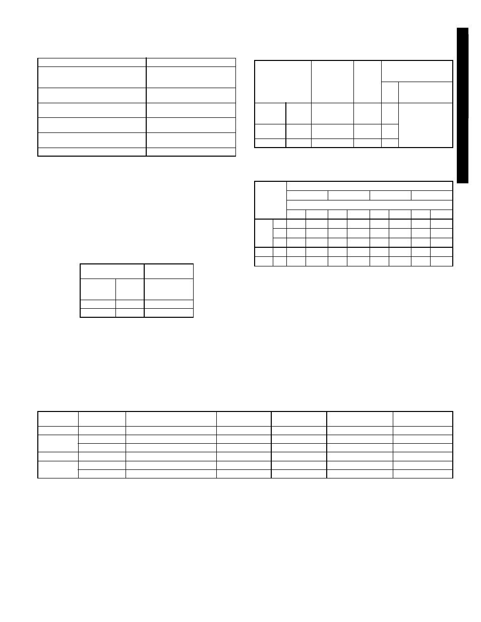
OPERATING LIMITS
NOTES:
1. Select air handler at no less than 300 cfm/ton (nominal condens-
ing unit capacity).
2. Total combined draw of the field-supplied liquid line solenoid valve
and air handler fan contactor must not exceed 22 va. If the speci-
fied va must be exceeded, use a remote relay to control the load.
1. LIQUID LINE — For applications with liquid lift greater than
20 ft, use
1
/
2
-in. liquid line where
3
/
8
in. is shown; use
5
/
8
-in.
liquid line where
1
/
2
in. is shown. The maximum liquid lift is
60 ft.
MAXIMUM REFRIGERANT CHARGE
2. REFRIGERANT PIPING — It is recommended that the
refrigerant piping for all commercial split systems include a
liquid line solenoid valve, a liquid line filter drier, and a sight
glass.
For refrigerant lines longer than 75 lineal ft, a liquid line
solenoid valve and a suction accumulator are required.
Refer to the Refrigerant Specialties table.
MINIMUM OUTDOOR-AIR OPERATING
TEMPERATURE
*Unit has one step of unloading.
REFRIGERANT PIPING SIZES
LEGEND
L — Liquid Line
S — Suction Line
NOTES:
1. Pipe sizes are based on a 2
° F loss for liquid and suction lines.
2. Pipe sizes are based on the maximum linear length, shown for
each column, plus a 50% allowance for fittings.
3. Charge units with R-22 in accordance with unit installation
instructions.
REFRIGERANT SPECIALTIES PART NUMBERS
*Bushings required.
Maximum Cooling Outdoor
115 F
Minimum Outdoor Ambient
See Minimum Outdoor-Air
Operating Temperature
table at right.
Minimum Return-Air
Temperature
55 F
Maximum Return-Air
Temperature
95 F
Normal Acceptable Saturation
Suction Temperature Range
25 to 55 F
Maximum Discharge
Temperature
275 F
Minimum Discharge Superheat
60 F
UNIT
SIZE
R-22 (lb)
569D
072
17.3
090
34.2
120
34.2
576C
120
34.2
569F
120
(2) 17.1
UNIT
SIZE
COMPR
CAPACITY
COND
TEMP
(F)
MINIMUM
OUTDOOR TEMP
(F)
Std
With
Motormaster
®
Control
569D
072
100%
90
35
–20
090
100%
90
35
120
100%
90
35
576C
120*
100%
90
35
67%
80
35
569F
120
100%
90
35
UNIT
SIZE
LINEAR LENGTH OF PIPING — FT
0-25
25-50
50-75
75-100
Line Size (in. OD)
L
S
L
S
L
S
L
S
569D
072
3
/
8
1
1
/
8
3
/
8
1
1
/
8
3
/
8
1
1
/
8
3
/
8
1
1
/
8
090
3
/
8
1
1
/
8
1
/
2
1
1
/
8
1
/
2
1
1
/
8
1
/
2
1
1
/
8
120
1
/
2
1
3
/
8
1
/
2
1
3
/
8
1
/
2
1
3
/
8
1
/
2
1
3
/
8
576C 120
1
/
2
1
3
/
8
1
/
2
1
3
/
8
1
/
2
1
3
/
8
1
/
2
1
3
/
8
569F 120 (2)
3
/
8
(2) 1
1
/
8
(2)
3
/
8
(2) 1
1
/
8
(2)
3
/
8
(2) 1
1
/
8
(2)
3
/
8
(2) 1
1
/
8
UNIT
LIQUID LINE
SIZE (in.)
LIQUID LINE
SOLENOID VALVE (LLSV)
LLSV
COIL
SIGHT
GLASS
FILTER
DRIER
SUCTION LINE
ACCUMULATOR
569D072
3
/
8
200RB5T3M
AMG/24V
AMI-1TT3
P502-8304S*
S-7063S*
569D090
3
/
8
200RB5T3M
AMG/24V
AMI-1TT3
P502-8304S*
S-7063S*
1
/
2
200RB5T4M
AMG/24V
AMI-1TT4
P502-8304S
S-7063S*
569D120
1
/
2
200RB6T4M
AMG/24V
AMI-1TT4
P502-8307S*
S-7063
576C120
1
/
2
200RB6T4M
AMG/24V
AMI-1TT4
P502-8307S*
S-7063
3
/
8
200RB5T3M Qty 2
AMG/24V Qty 2
AMI-1TT3 Qty 2
P502-8304S* Qty 2
S-7061 Qty 2
50
TF
Q
0
0
4
-0
1
2
5
6
9D
07
2-
12
0
, 57
6C
12
0
, 5
6
9F
1
2
0