BASELINE Motorcycle Ready Addendum User Manual
Page 4
4 •
BaseLine
5a.
Prior to placing the wheel on the table top to
clamp, observe the style and strength of the wheel
and adjust the clamp pressure as necessary using the
pressure regulator and gauge. Thin spun aluminum rims
sometimes used on ATV and motorcycle are some-
times delicate and a reduced air pressure should be
considered verses cast aluminum and steel wheels that
can support more clamping force.
5b.
Next, observe the rim size from the tire, i.e. 15,
16, 17, etc. Using the clamp pedal, place the clamp valve
in the JOG IN position for prelocating the clamps to
the rim diameter. Accomplish this by moving the pedal
from the UP position to the 1/2-DOWN location. Then
JOG the pedal DOWN allowing the clamps to move
inward until the pointer on the clamps align with the rim
diameter on the table top decal. It may be necessary to
relocate the clamps on the clamp carriers. Each clamp
should be in the same position before prelocating the
clamps.
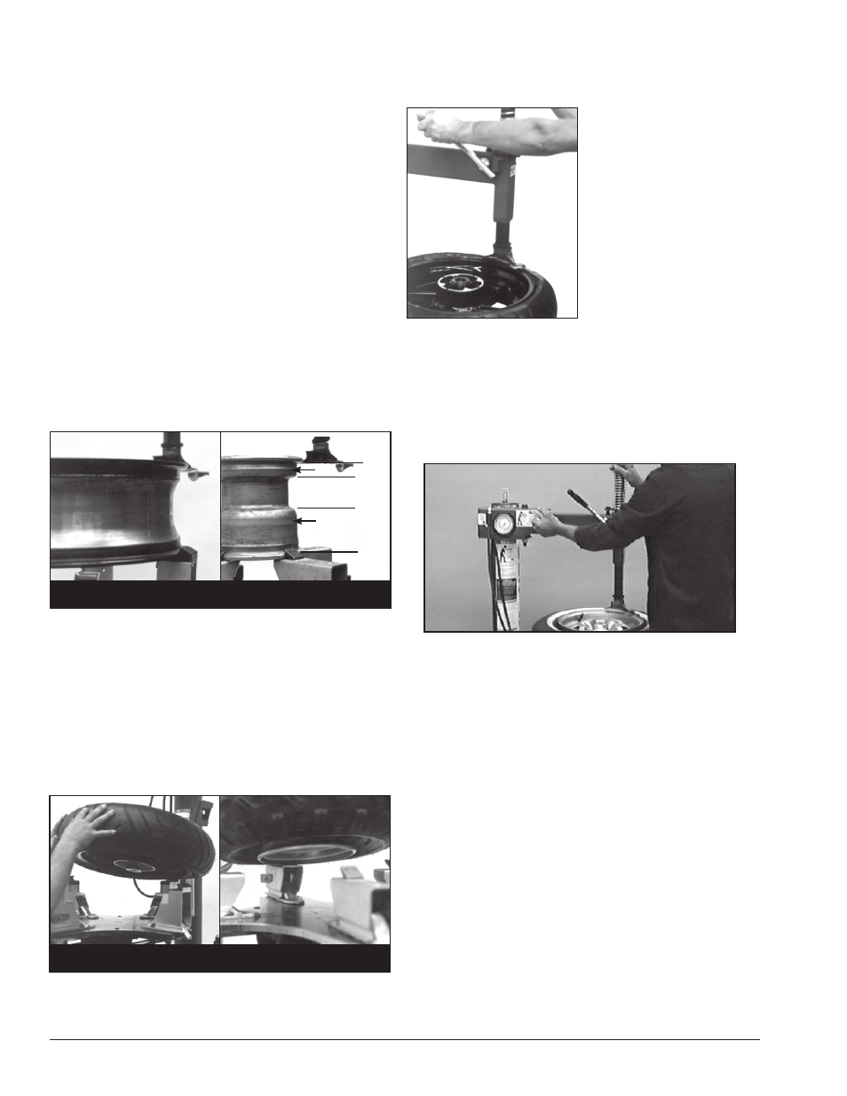
5c.
Determine the mounting side of the wheel. The
mounting side is the narrow side of the drop center.
(Tire removed in Figure 4 for clarity.)
Figure 4 - Determining Mounting Side of Wheel
6.
Place tire/wheel assembly on table top with mount-
ing side up (Figure 5). Use the clamp control pedal to
move the clamps inwards (push pedal down) or out-
wards (toggle pedal up). Clamp motorcycle and ATV
wheels from the outside (clamps push inwards against
the outside rim edge). Place rim flange into rear clamp
and slowly move the other clamps inward until they
contact the rim. Observe closely to prevent tire/wheel
damage.
Figure 5 - Place Tire/Wheel Assembly on Table Top
7.
Move the swing arm into position. Pull the lock-
ing handle forward to release the slide. Push down
on the top of the vertical slide to move the demount
tool into contact with the
rim edge. Push the lock-
ing handle back to lock the
slide into place. As the
slide is locked, the mount/
demount tool will move
upward approximately 1/8
inch from the rim edge.
Note: On plastic mount/
demount tool, the upward
movement should be
limited to 1/16-inch maxi-
mum.
Figure 6 - Position Mount/Demount Tool
8.
The mount/demount tool roller should be in contact
with the rim edge. Turn the swing arm adjusting knob
to move the tool away from the rim 1/8 to 1/4 inch.
On expensive and polished rims, it is recommended a
plastic bootie (p/n 8183373) be used over the mount/
demount tool roller.
Figure 7 - Adjust Swing Arm to Position Tool Roller
9.
Check tool positioning. Mount/demount tool should
be positioned with 1/8 to 3/16” clearance between the
top of the rim edge and the bottom of the tool (with
plastic mount/demount tool it is recommended the ver-
tical clearance be limited to a maximum of 1/16-inch),
and 1/8 to 1/4 inch clearance between the rim edge and
the tool. This clearance will be maintained as long as the
locking handle and adjustment knob are not changed.
The operator may swing the arm out of the way and
back into place again without needing to reposition the
tool (when changing a set of the same wheels).
Motorcycle
Motorcycle
ATV
ATV
Motorcycle
Motorcycle
ATV
ATV
Narrow Side
Drop Center
Long Side