APG PT-400 Pressure Transducer user manual User Manual
Page 6
PT-400
Rev. C, 4/13
6
Automation Products Group, Inc.
APG...Providing tailored solutions for measurement applications
Tel: 1/888/525-7300 • Fax: 1/435/753-7490 • www.apgsensors.com • [email protected]
Power supply voltage must be sufficient to maintain a minimum of 9 VDC at
the transducer/transmitter terminals after “dropping” voltage across RL at full
scale current (20 mA), see Figure on page 6. Example: If RL = 250 ohm then
“drop” is 0.02 Amps X 250 ohm = 5 volts. Therefore power supply minimum is
5 V + 9 V = 14 V
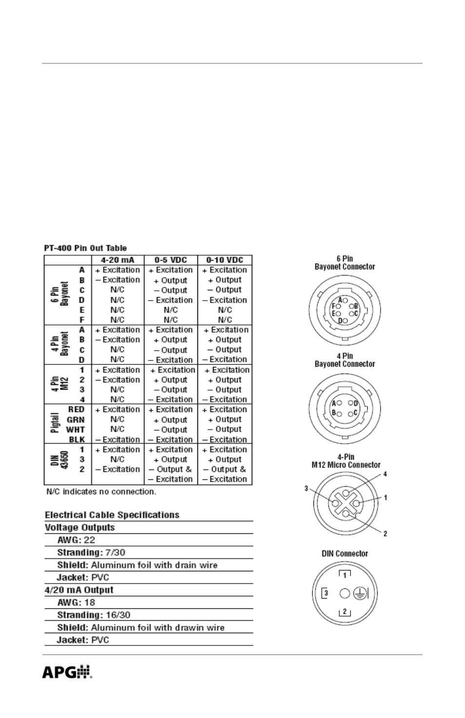
4. Wiring Information
Below, and on the next page, are the pin out diagrams, circuit diagrams, and
pin out table for the 4-20 mA, 0-5 VDC and 0-10 VDC circuits, as needed to
assist you in wiring your transducer.
This manual is related to the following products: