Stereo input channel 8, Balance control, Mute switch – Allen&Heath ZED-436 User Manual
Page 21: Auxes 1 & 2, Auxes 3 & 4, Auxes 5 & 6, Pfl switch, Routing switches, Signal & pk! led, Fader
Allen & Heath 21 ZED-4 BUS User Guide
8
9
10
11
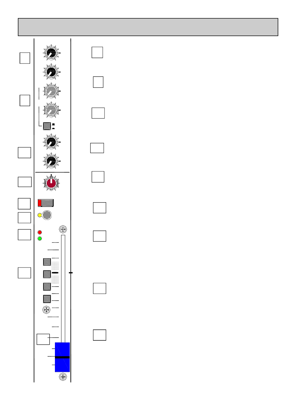
Balance control
The Balance control varies the relative levels between the left and right
channels.
12
Mute Switch
Mutes the signals to the main L R, M and Group buses as well as the Aux
sends.
13
17-18
+6
AUX1
PRE
+6
AUX2
PRE
+6
AUX3
+6
AUX4
PRE
POST
O
O
O
O
O
O
O
O
+6
AUX5
POST
+6
AUX6
POST
O
O
O
O
ODD
BAL
L
EVEN
R
=
MUTE
PFL
PK !
SIG
10
OO
30
20
0
M
L-R
1-2
3-4
STEREO INPUT CHANNEL
8
Auxes 1 & 2
Auxes 1 & 2 send a mono sum of the stereo channel left & right signals
sourced from pre-fader.
Auxes 3 & 4
Again, a mono sum of the stereo channel left & right signals, the source be-
ing switchable pre or post fader.
Auxes 5 & 6
Auxes 5 & 6 take their source from a mono sum of the stereo channel left &
right signals after the fader.
9
10
11
12
PFL Switch
The PFL (Pre-Fade Listen) switch sends a mono sum of the stereo channel
channel signal to the PFL bus.
Routing Switches
The routing switches connect the post-fade signal to the mix buses via the
balance control for L_R and the groups. For minimum noise from the mix
bus summing amplifier, leave the switches in their up positions if the channel
signal is not required on the bus.
Signal & PK! LED
The Signal LED illuminates dimly at a threshold of –16dB on either left or
right channels and gets brighter with higher level signal. The source for the
signal & peak LED’s is just after the EQ IN switch.
The PK! LED illuminates when the signal just after the EQ IN switch is
within 5dB of clipping.
Fader
The 100mm fader affects the level of the channel signal to the left & right,
mono and group buses and Auxes 5 & 6. Also Auxes 3 & 4 if switched to
post-fade. There is 10dB of gain at the top and the unity gain position is
marked by “0”.
13
14
14
15
15
16
16