Allen & heath firewire control panel – Allen&Heath FireWire Interface User Manual
Page 12
Allen & Heath 12 GS_R24 FireWire/ADAT Module User Guide
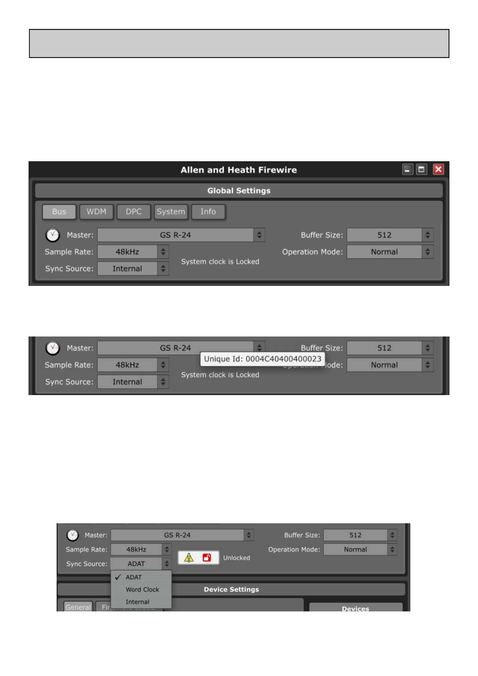
When the mouse pointer hovers over the Master combo box, a ToolTip will display the IEEE1394 unique ID of the device.
The sample rate and sync source always refer to the selected clock master. It is possible to connect a ZED-R16 to the GS-R24,
in which case one of them will be the clock master and the other the slave. When only one Allen & Heath device is connected,
it will always be the clock master. When the device is not locked (synchronised and working at the selected sample rate), a
warning icon will appear under the Master display box. Hovering the mouse pointer over the text will display a message stating
whether the master device is locked or not. The GS-R24 FireWire/ADAT module can be synchronised to an external clock
source by selecting Word Clock and connecting to the BNC connector, or synchronised to an ADAT source by selecting
ADAT as the Sync Source and plugging an ADAT source into Input 1-8. Here (below), the GS-R24 device (clock Master) is set
to synchronise from the ADAT input stream which is not plugged in, therefore the GS-R24 device is not locked or synchro-
nised to the master clock.
The control panel is divided into two main sections, Global Settings and Device Settings.
Global Settings
All system related settings are here, grouped into five Tabs for Windows, three for the Mac version.
Bus Tab:
Contains controls for choosing the system clock master device, sample rate, synchronisation source, buffer size, and opera-
tion mode.
ALLEN & HEATH FIREWIRE CONTROL PANEL