Remote control of the levels – Allen&Heath GR1 SERVICE MANUAL User Manual
Page 16
GR1
USER GUIDE
13
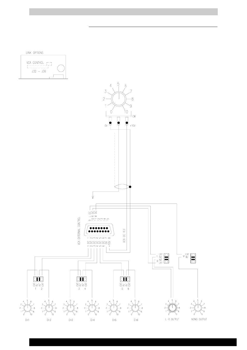
REMOTE CONTROL OF THE LEVELS
Each of the 6 channels and the main L,R and M outputs are fed through high
performance VCA (voltage controlled amplifier) circuits. These are controlled
individually either by the front panel level controls or by external DC voltages
connected to the REMOTE DC connector according to the setting of the internal
jumper links as shown below.
Control Voltages are:
+10V DC
= channel fully on
0V
= channel off
A buffered +10V DC reference voltage is
provided on the REMOTE DC connector.
This may be connected to a potentiometer for
remote level control. The recommended
potentiomenter is 10K ohms reverse (antilog)
logarithmic.
Use screened cable to minimise interference
pickup.
NOTE: Any references to control voltages of
0V to -9V should be substituted with the
above.
LINK OPTIONS
INT/EXT DC CONTROL
The inner links set internal front panel level
control, the outer links set external level
control.
+10V DC INT/EXT VOLTAGE
The +10V DC voltage can be derived inter-
nally or externally by setting the link on the
remote connector circuit board.