Configuration – Allen&Heath GR1 SERVICE MANUAL User Manual
Page 11
GR1
USER GUIDE
8
CONFIGURATION
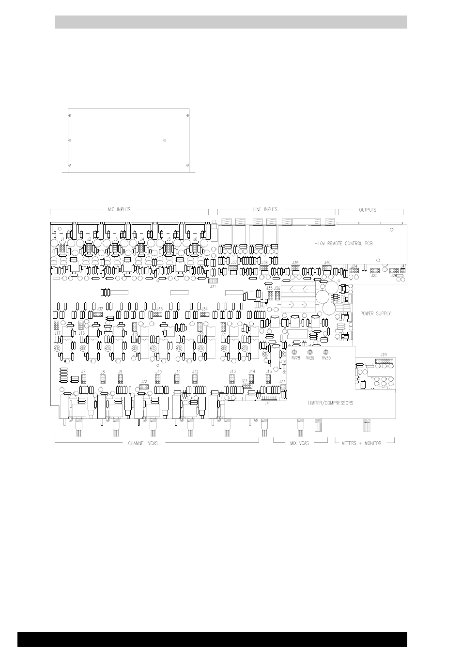
The GR1 offers unique flexibility in its ability to be configured to satisfy the exact requirements of each installation.
This is done by setting internal jumper links and calibration trimmers which determine the operating levels, signal
routing, and mode of operation of the ducking, alarm and compressor/limiter systems. These are accessed by
removing the top cover. The option link layout is shown above and in the system block diagram. Once installed the
settings become tamperproof and only the front panel controls are available to the user making the unit extremely
easy to operate.
Configuration should only be carried out by a competent installation engineer. Apply caution when powering the
unit with the top cover removed. Only the compressor/limiter threshold trims may need adjustment with power
applied. The following pages detail the installation options.
Remove the 6 crosshead screws securing the
top cover to the chassis. Lift off the cover to
gain access to the options. Apply caution if
powering the unit with the cover removed.