2gs1 – Allen&Heath GS1 USER GUIDE User Manual
Page 9
1
2
3
4
5
6
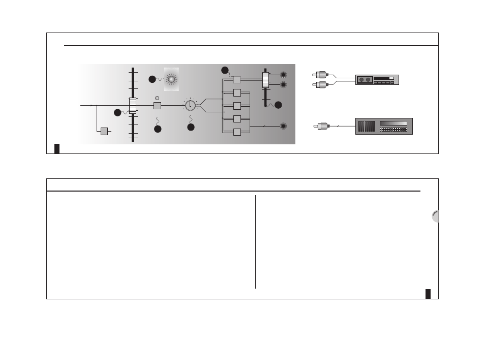
PFL
The PFL switch is used for monitoring individual channel signals. Use PFL to set
the optimum channel level from the Mic/Line gain control or Hi/Lo switch. The PFL
active LED on the master section indicates when any PFL switch is active.
The level to the LR buss or groups (routing) is set using the main 100mm
channel fader. There is no need for group master levels as all routed channels can
easily be set for the optimum tape level.
The ‘Channel On’ switch mutes or unmutes the signal to the LR buss and groups.
This is a momentary switch and is controlled by the internal micro-processor and
via MIDI.
P
AN
Pan will route the signal proportionately to Left/(Odd) Right/(Even) group numbers.
R
OUTING
The routing matrix directs the channel signal to either the LR buss (through the LR
master fader to the 2 track out), or direct to the individual group output sockets.
The LR fader trims the overall mix level to the 2 track master outputs.
PFL, P
AN
, M
UTE AND
R
OUTING
14
2
GS1
N
OTES
PAN
CHANNEL
ON
PFL
CHANNEL PATH
STEREO INPUT
(2 TRACK OUT)
MAIN OUT
GROUP OUT
LR FADER
PFL
ACTIVE
8
FADER
1-2
3-4
5-6
7-8
1
2
3
PFL, PAN, CHANNEL ON (MUTE) & ROUTING
0
10
¥
-30
-20
-15
-10
-5
0
+5
+10
-5
0
+5
+10
4
L-R
5
6
PHONO
L IN
R IN
1 of 8
L
R
IN
13
S
ECTION
2 S
IGNAL
P
ATHS