Allen&Heath Scepter SERVICE MANUAL User Manual
Page 8
Audio Owner Manual
Section 5
brought out to holes in the circuit board allowing you to feed an Aux output or other
signal to the Stereo Out. Solder a wire between the hole pad and the desired signal
point and move the header to the Ext position.
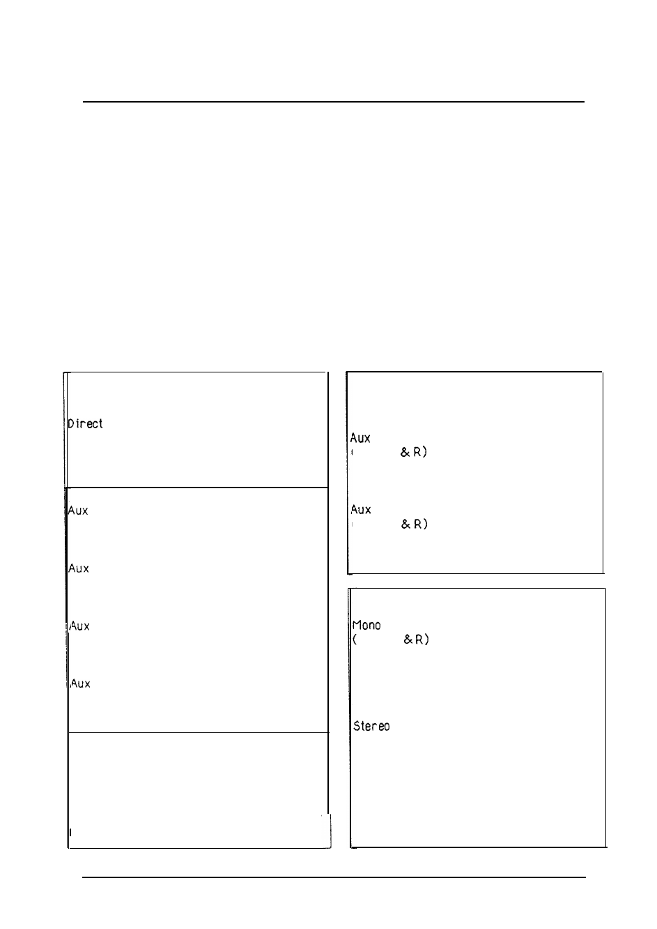
OPTIONS TABLE
All the possible Scepter user options are listed in the table below with the
factory defaults indicated with an X. Diagrams on the following pages show the
Scepter circuit cards and where the various jumper links and default jumpers are
located.
INPUT CHANNEL
Out
Post-Fader/Post-Mute X
Post-Fdr/Pre-Mute
Pre- Fader
A Source
Post-Fader
Pre-Fader
Pre-EQ X
B Source
Post-Fader
Pre- Fader
Pre-EQ X
C Source
Post-Fader X
Pre-Fader
Pre-EQ
D Source
Post-Fader X
Pre- Fader
Pre-EQ
Pre-EQ Source
Post-Insert/Post-HPF X
Post-Insert/Pre-HPF
Pre-insert
Pre-EQ Mute
Mute With Channel X
No Mute With Channel
L/R GROUP
Stereo Return Aux Feeds
A Source
(Mixes L
Left Rtn: Post-Level
Left Rtn: Pre-Level X
Right Rtn: Post-Level
Right Rtn: Pre-Level X
B Source
(Nixes L
Left Rtn: Post-Level
Left Rtn: Pre-Level X
Right Rtn: Post- Level
Right Rtn: Pre-Level X
MASTER
Out
Mixes L
Left: Pre-Insert X
Left: Post Insert
Left: Post-Fader
Right: Pre-Insert X
Right: Post Insert
Right: Post- Fader
Out Left
Left: Pre-Insert X
Left: Post Insert
Left: Post-Fader
Ext PC Pad
Stereo Out Right
Right: Pre-Insert X
Right: Post Insert
Right: Post- Fader
Ext PC Pad
36