Allen&Heath Scepter SERVICE MANUAL User Manual
Page 3
Audio Owner Manual
Section 5
to be carried out.
a
Free the DC power XLR-5 pin insert from its metal shell by using a small
screwdriver to loosen the XLR setscrew (anti-clockwise). The insert can then
be pulled out the back of the XLR shell. The DC wires to the Master card will
remain attached to the insert.
9
Remove the loosened plastic nuts from the
jacks.
10
Remove the 2 fixing screws from each XLR jack.
11
Lift the Rear panel off the circuit cards.
--
The Circuit cards are now accessible for changes to the jumper links or repair
work. If the main IDC 20 way ribbon harness is removed for service, use care when
it is replaced. Make sure that all pins on all Circuit cards are correctly inserted into
the IDC sockets; it is easy to bend a pin or mistakenly shift over one pin when
putting a socket on. When re-assembling the Scepter, follow the above steps in
reverse order.
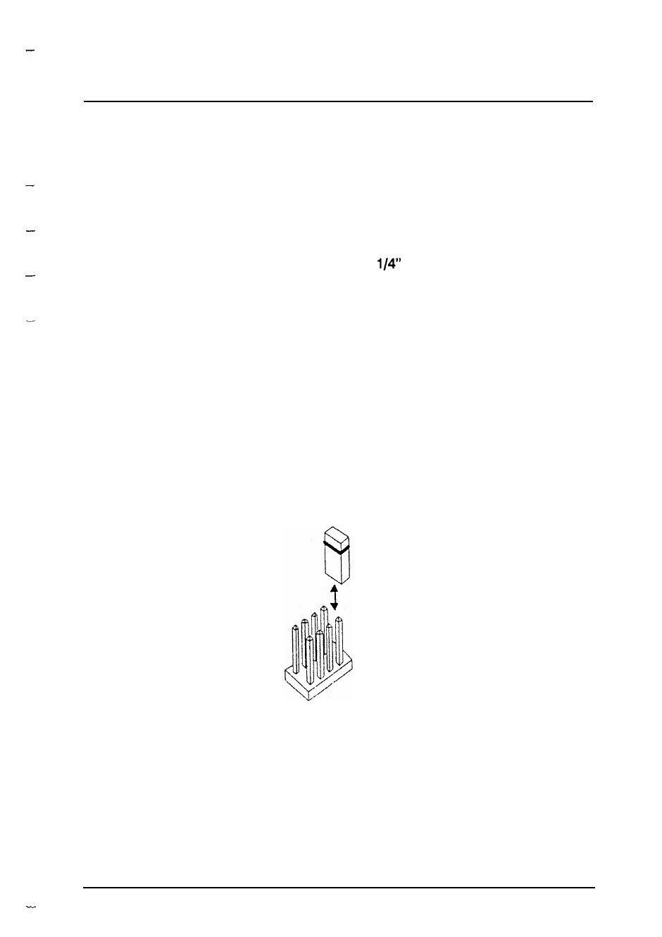
The diagram below shows a header and Jumper link arrangement.
REMOVABLE
JUMPER
DUAL ROW HEADER
31
- GL2800M SERVICE MANUAL (13 pages)
- GL2800M USER GUIDE (23 pages)
- 21 Series (18 pages)
- GL3800 (44 pages)
- Xone V6 (42 pages)
- Xone S6 (42 pages)
- Xone DX (67 pages)
- Xone 3D (42 pages)
- Xone 32 (25 pages)
- Xone 1D (2 pages)
- Xone 2D (34 pages)
- XB 14 (40 pages)
- WZ20 8 2 SERVICE MANUAL (35 pages)
- WZ16 2DX (28 pages)
- WZ16 2 (16 pages)
- WZ14-4-2 MK2 (24 pages)
- WZ14-4-2 (21 pages)
- WZ 20S USER GUIDE (35 pages)
- WZ 20S SERVICE MANUAL (23 pages)
- SR Plus OWNER MANUAL (1 page)
- Scepter USER GUIDE (42 pages)
- RPS9 (7 pages)
- RPS14 (18 pages)
- RPS10 (7 pages)
- ML5000 SERVICE MANUAL (135 pages)
- ML5000 SIDECAR USER GUIDE (4 pages)
- ML5000 USER GUIDE (60 pages)
- ML4000 USER GUIDE (4 pages)
- ML4000 USER GUIDE (56 pages)
- ML4000 SERVICE MANUAL (91 pages)
- ML3000 Application Guide (2 pages)
- ML3000 USER GUIDE (48 pages)
- ML3000 Using Guide (2 pages)
- ML3000 VCA (3 pages)
- MixWizard3 16-2 (30 pages)
- MixWizard3 14-4-2 (27 pages)
- MixWizard3 12M (22 pages)
- GS3000 (40 pages)
- GS1 SERVICE MANUAL (38 pages)
- GS1 USER GUIDE (22 pages)
- GR8A (11 pages)
- GR1 USER GUIDE (17 pages)
- GR1 SERVICE MANUAL (48 pages)
- GL4800 USER GUIDE (62 pages)