Using the oscillator / noise generator, Using pfl / afl, Using inserts – Allen&Heath GL2800M USER GUIDE User Manual
Page 17
G
G
G
GL
L
L
L2
2
2
28
8
8
80
0
0
00
0
0
0M
M
M
M
17
Allen & Heath
Using the Oscillator / Noise Generator
The GL2
GL2
GL2
GL28
8
8
800
00
00
00M
M
M
M
includes a useful signal generator able to produce a pure 1kHz sine
wave tone, or a pink noise test source. This is invaluable in testing the
system components and setting up correct gain structure. The
generator can be routed independently to the various console outputs.
Use the 1kHz tone to line up the connected equipment. For example,
a mix output to an in-ear transmitter or effects send/return loop. Route
the tone to the mix you wish to align. Set the mix master fader to ‘0’.
Press the mix TB switch to route the tone to this mix. Turn up the
OSC/NOISE level until the mix meter reads ‘0’. Next, adjust the
destination equipment input trim so that its meter also reads ‘0’. The
connected equipment is now correctly aligned to the operating level of
the console. You can patch the tone to other equipment by enabling
the EXT TB switch and using the rear panel EXT TB/OSC output.
Use the Pink Noise generator to check the signal routing and
loudspeaker response. ‘Pink noise’ is a random signal that contains
all audio frequencies and is therefore a very good test source. Unlike
‘white noise’ which has equal energy per Hz and sounds like system
or inter-band tuner hiss, pink noise has equal energy per octave, a
response that matches the logarithmic way our ears perceive sound.
You can hear all the frequencies clearly from deep bass, through mid
to treble. This means you can route the noise to a speaker system
and quickly hear if one of the sub, mid or HF drivers is faulty. With the
noise sent to several speakers at the same time you can listen for
comb filtering, and the severe phasing effect which indicates that one
of the speakers may have its wires reversed. Adjust the swept
frequency mix HPF using the noise source to listen to the effect of
cutting the low frequencies in the monitors.
The GL2
GL2
GL2
GL28
8
8
800
00
00
00M
M
M
M signal generator is an invaluable tool for calibrating
and testing the system during setup. To prevent any unexpected
mishaps during the sound check or show, remember to disable it by
releasing the recessed ON switch once you have finished the testing.
We also advise that you always start the calibration with the
OSC/NOISE trim turned fully off so that you can bring it up gradually
without the risk of overloading the destination.
Using PFL / AFL
The input channels provide PFL (pre-fade
listen) so that each source can be checked using the meters and
wedge/IEM monitors before you bring the channel fader up. You can
use PFL while the channel is muted to prevent the signal reaching the
monitors until you have checked it and are ready. All the mix outputs
provide AFL (after-fade listen) so that you can check the exact level
leaving the console. The AFL switch gets its source before the output
mute so that you can check the signal before you send it to its
destination.
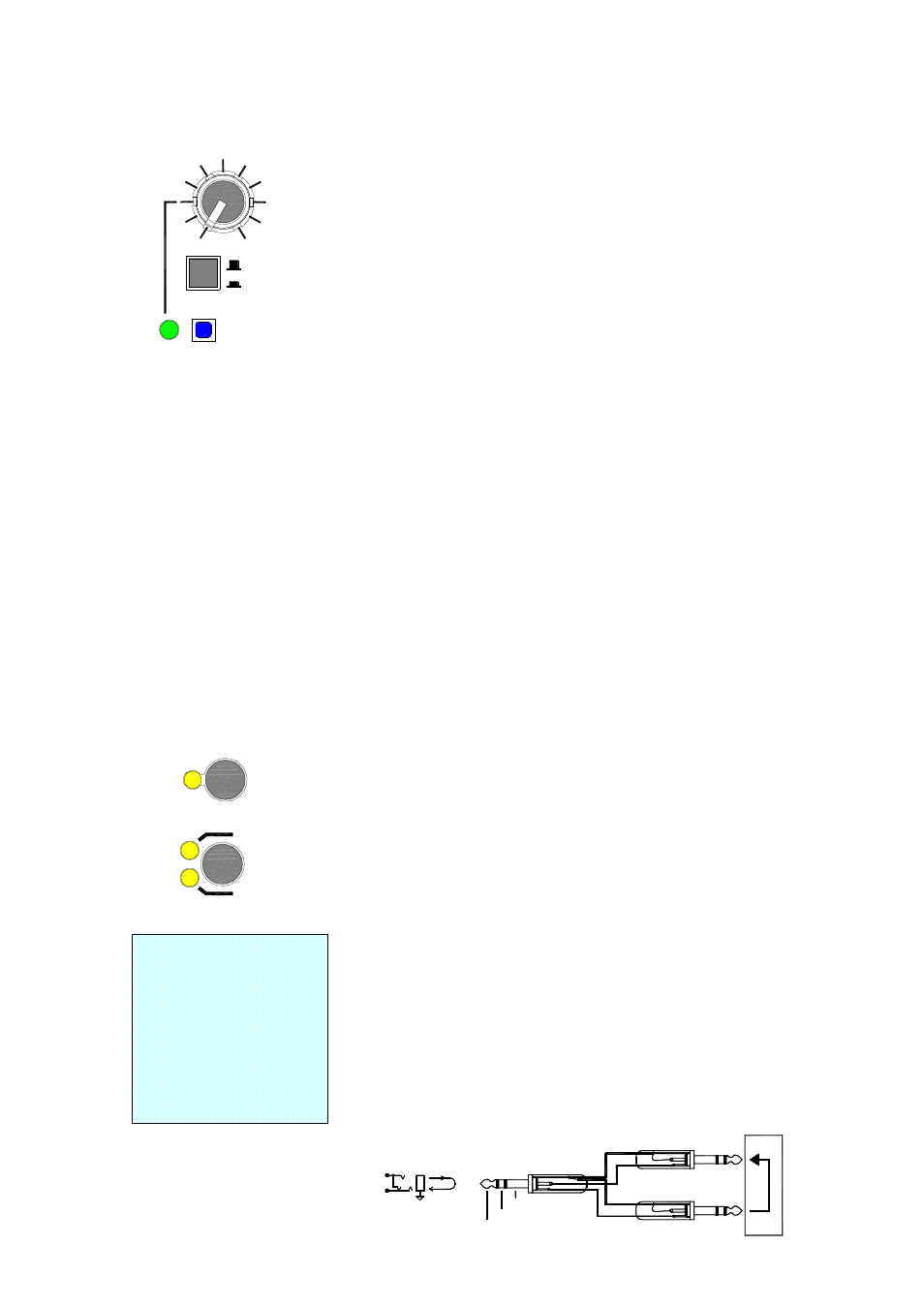
Using Inserts
The GL28
GL28
GL28
GL2800
00
00
00M
M
M
M channel inserts operate at 0dBu,
the output inserts operate at -2dBu. In practice this makes little
difference as long as the inserted equipment is intended for line level
operation (-6 to +4dBu). Simply set the gain through the device to
unity (0dB) with the bypass switch pressed (if available). With the
effect switched in, use the processor output level trim or make-up gain
to make any further adjustments needed. This keeps the gain
structure correct through the channel signal path. With nothing
plugged into the insert, the channel signal is routed through a
switching (‘normalling’) contact in the socket. As soon as a jack is
plugged into the socket the contact is opened and the signal path
broken so that the external device can be patched in series with the
signal.
☺
If you suspect the insert
socket
to
be
faulty
or
intermittent through excessive
wear or contamination, test for
this by plugging in a jack with
its tip shorted to its ring
contact. This bypasses the
contact in the socket. Clean
using
suitable
electrical
contact cleaner.
1kHz OSC
PINK NOISE
ON
MAX
MIN
OSC/NOISE
A
WEDGE
IEM
AFL
PFL
GROUND
RETURN
SEND
RETURN
OUT
IN
SEND
LINK RING TO SLEEVE TO UNBALANCE
SEND
INSERT
RETURN
TIP
RING