The input channel, Channel input, Channel preamp – Allen&Heath GL2800M USER GUIDE User Manual
Page 11: Phantom power, Built-in mic splitter, Gnd lift, Insert
G
G
G
GL
L
L
L2
2
2
28
8
8
80
0
0
00
0
0
0M
M
M
M
11
Allen & Heath
The Input Channel
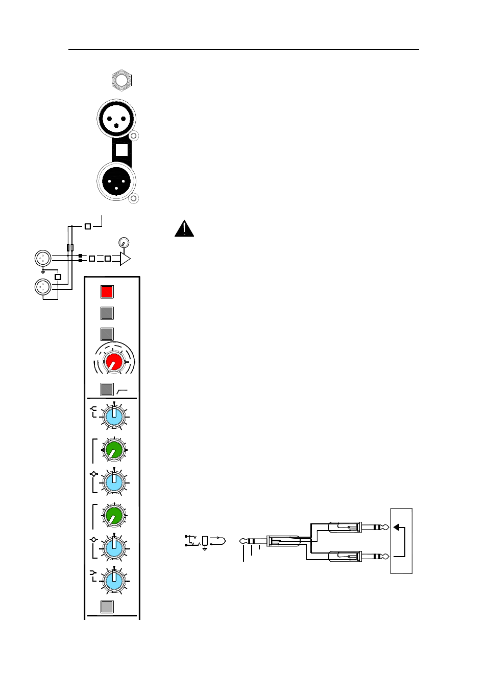
CHANNEL INPUT
Balanced XLR input pin 2 hot. Accepts mic or
line level signals. For unbalanced sources use a cable or adapter that
connects XLR pin 3 to pin 1.
CHANNEL PREAMP
54dB gain range with 20dB pad to accept
signals from -60dBu to +14dBu nominal. Press PAD for hot signals up to
+34dBu max. Press HPF to switch in a 12dB/octave 100Hz lo cut filter.
Press POLARITY to invert the signal for working with a pin 3 hot source,
correcting a reverse wired cable, bottom miking a snare drum and so on.
Reversing polarity may help certain situations where feedback is a
problem.
PHANTOM POWER
Press +48V for phantom power via 6.8k ohm
resistors to pins 2 and 3 for microphones such as condensers which
require phantom powering.
WARNING: Do not connect unbalanced sources or cables to
the XLR input when 48V phantom power is selected. To avoid loud
clicks always turn the channel off by pressing MUTE when switching
+48V on or off, and when plugging or unplugging cables.
If you are working with separate monitor and FOH consoles then phantom
power may be supplied by either or both consoles without damage.
Typically the monitor console provides the power because the monitor
engineer would be closer to the stage patch.
BUILT-IN MIC SPLITTER
Passes the XLR input through to an XLR
output to split the signal to another console such as FOH or recording.
This is a passive split. The GL2800
GL2800
GL2800
GL2800M
M
M
M does not need to be turned on
for the split to work.
GND LIFT
Disconnects the pin1 ground connection between the input
XLR and the split output XLR. Press this if there is a problem with a venue
ground loop causing audible hum when connecting the splitter to a
second console. To isolate the audio ground between the consoles make
sure you select all the channel ground lift switches.
INSERT
A single 3-pole TRS jack carries the unbalanced insert signal
for each channel and main mix output. Tip = send, Ring = return, Sleeve
= common ground. The channel inserts are post-HPF, pre-EQ and
operate at 0dBu. Use these to patch in line level signal processing
equipment such as compressors, gates or outboard EQ. The wiring of a
suitable cable is shown in the diagram.
EQ
4 band channel EQ with swept frequency mids. The EQ is post-
insert so that any inserted processing will be affected by these controls.
The channel pre-fade aux sends are configured post-EQ as standard.
INSERT
SPLIT
GND LIFT
INPUT
GROUND
RETURN
SEND
RETURN
OUT
IN
SEND
PROCESSOR
LINK RING TO SLEEVE TO UNBALANCE
SEND
INSERT
RETURN
TIP
RING
60 40
-14
6
30
40
50
0
20
GAIN
100Hz
POLARITY
+48V
HPF
80Hz
12k
EQ IN
HF
+15
4k
15k
6k
1k
-15
500Hz
700
HM
3k
+15
250
1k
400
-15
70
35Hz
LM
45
180
+15
+15
-15
LF
-15
PAD
POL
48V
PAD
-20dB
GAIN
-
+
2= +
IN
SPLIT
LIFT
PHANTOM POWER