The engineer’s toolbox, Phones out, Tb mic – Allen&Heath GL2800M USER GUIDE User Manual
Page 15: Osc/noise generator, Pink noise / 1khz osc, Ext tb, Talk, Latch, Mute groups, Headphones follow iem
G
G
G
GL
L
L
L2
2
2
28
8
8
80
0
0
00
0
0
0M
M
M
M
15
Allen & Heath
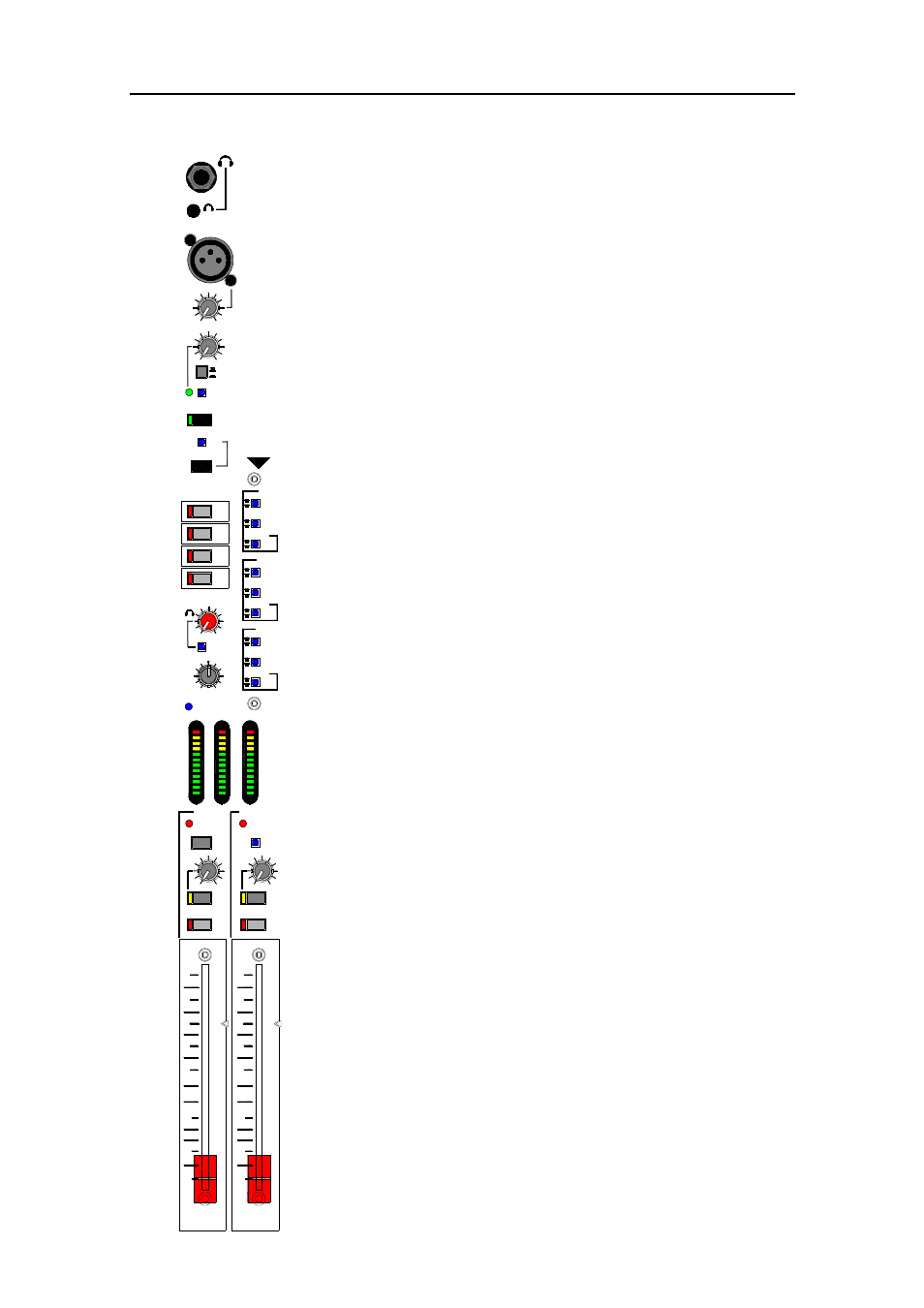
The Engineer’s Toolbox
The GL28
GL28
GL28
GL2800
00
00
00M
M
M
M provides a comprehensive combination of facilities
to help the monitor engineer set up and keep control of the multiple
wedge/in-ear stage environment. Includes the engineer’s monitors,
headphones sockets, talkback section, built-in oscillator/noise test
generator, mute group masters and the global settings configuration
switches.
PHONES OUT
Both a ¼” and a 3.5mm socket are provided here
for plugging in standard headphones and mini-jack ear pieces and in-
ear sets. An alternative ¼” socket is provided under the armrest.
TB MIC
Plug in a cable or gooseneck vocal microphone to talk to
the performers via their monitors. +48V phantom power is provided.
This may be disabled by resetting an internal jumper. Adjust the mic
level using the TALKBACK trim control.
OSC/NOISE GENERATOR
The generator is turned on or off
using a recessed switch to protect it from accidental operation. When
you have finished using the generator turn it off to avoid test signal
during the show. Adjust the level using the OSC/NOISE trim control.
The test signal is routed to a mix output as soon as its associated TB
switch is pressed.
PINK NOISE / 1kHz OSC
Select either the pink noise or 1kHz
tone as the test source. Use the tone when calibrating equipment
levels. Use pink noise when testing speaker drivers and polarity.
EXT TB
Routes the talkback/generator to the rear panel EXT
TB/OSC socket. Balanced line level XLR output to drive a long cable
run to a remote location, for example to communicate with the
engineer at the FOH console. The output could also be used to patch
the generator to test console channels or other audio equipment.
TALK
Press this momentary switch to route the talkback mic to any
output which has its TB switch selected. To prevent possible
feedback the engineer’s wedge output is dimmed (attenuated) by
20dB when TALK is pressed. The generator is dimmed by 12dB for
intelligibility, for example when talking to a monitor being tested.
LATCH
This recessed mode switch overrides the TALK switch to
permanently enable the talkback mic when using a switched hand
held microphone. Simply activate the switch on the microphone when
you want to talk to enabled destinations. The TALK switch still
provides a manual dim function.
MUTE GROUPS
Press one or more of these master switches to
mute all inputs assigned using the channel M1-4 switches.
HEADPHONES FOLLOW IEM
Set this recessed mode switch
to change the headphones source to follow the IEM monitor system.
PFL TRIM
Adjust the PFL signal level to the headphones and
monitor outputs to match your average AFL level. Range from -12dB
to +6dB with centre detented 0dB position for normal operation.
Does not affect the PFL meter reading.
IEM MASTER
Provides fader, mute, pre-fade meters, mono
summing of the stereo signal and external input switch and level trim.
Selecting a channel PFL overrides any current AFL selection, indicated
by the PFL ACTIVE LED.
WEDGE MASTER
Provides fader, mute, pre-fade meter and
external input switch and level trim. Select the recessed PFL ON
switch if you want to check PFL in the wedge monitor. PFL overrides
any current AFL selection.
MIX
1-8
STEREO
MONO
9-12
13-16
L
K
J
I
H
G
PRE
POST
IEM
WEDGE
MIX
STEREO
MONO
PRE
POST
IEM
WEDGE
MIX
STEREO
MONO
PRE
POST
IEM
WEDGE
MUTE GROUPS
AFL
AFL
AFL
F
E
D
MUTE
EXT
MUTE
EXT
ON
IN
EXT
IN
PFL ACTIVE
PFL
ON
WEDGE
IEM
PFL ACTIVE
MONO
L
R
M
MAX
MIN
MAX
MIN
EXT
ON
10
20
30
0
0
5
0
10
5
IEM
WEDGE
10
20
30
0
0
5
0
10
5
M1
M2
M3
M4
PHONES
TALKBACK MIC
MAX
MIN
TALKBACK
+9
+6
+3
0
-3
-12
-16
-30
-20
-9
-6
+16
+9
+6
+3
0
-3
-12
-16
-30
-20
-9
-6
+16
LATCH
TALK
1kHz OSC
PINK NOISE
ON
MAX
MIN
OSC/NOISE
0
+6
-12
TRIM
PFL
FOLLOW
POWER
EXT TB
C
B
A
MAX
MIN
IEM
GLOBAL
SETTINGS