Installation, Picture of typical venturi injector manifold – A2Z Ozone SP - Series User Manual
Page 6
If the pool volume is say 60000 liters then the pump should be capable of re-circulating the
water at a rate of at least 15000 liters per hour. This way, the total volume of water through the
pool will be passing through the injector at least once each 4 hour period. Less pump run time
for the minimum liters. Use Sodium Bromide if additional chemicals are required. Dosage is 20 g
per 1000 Liters of water every 6 months
INSTALLATION
OZONE GENERATOR PLACEMENT:
Install ozone generator in a clean, dry area with a good ventilation.
Ozone generator should be placed above any water level for the following reason; if you were to
lose pressure in the venturi vacuum, gravity will cause water to travel down the ozone output
tube and enter into the ozone generator. Please look at provided drawing for more information.
If water height less than 5 feet. (1.5 m)
Note:
Be sure to place ozone generator in room temperatures 40 and 100 Deg. F (4.5 to 38 Deg. C)
Select a location for the ozone generator that is as close as possible to the ozone injection point.
Situate the unit in a manner suitable for convenient electrical access. The MODEL SP-SERIES
enclosures is not rain proof, so it is important to choose a location that will keep the system
away from direct weather and excessive heat.
The mounting holes are located on the back of the ozone generator for convenient wall
mounting. Mounting hardware is not provided.
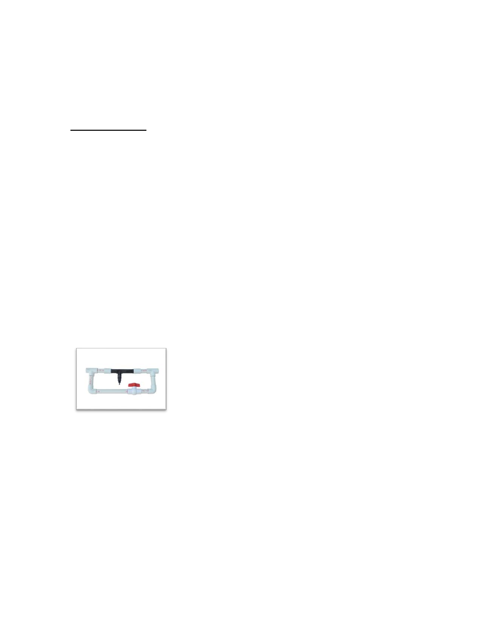
The basic installation method for the MODEL SP-Series system is INJECTOR MANIFOLD
PLUMBING CONNECTIONS. INJECTOR MANIFOLD MUST BE ASSEMBLED (ordered from our site
as well).
Picture of typical Venturi Injector Manifold
Refer to the ‘Venturi injector Installation’ diagram and follow the instructions below if the ozone
is being injected directly into the full flow of the pool’s return line:
• Identify the pool water supply line after the pump, filter and heater and Tap into this
point. The ozone injection point should be the last component in line and as far as
possible from the injection point of the residual chemical.
• Glue in the proper injector manifold, noting the direction of flow (indicated by an arrow
on the injector). Once the injector is installed, the vacuum may be adjusted as described
in the ozone operation Section.
6