Echo 99944200620 User Manual
Page 13
99944200620
ASSEMBLY
X7532093905
13
© 10/2013 ECHO Inc.
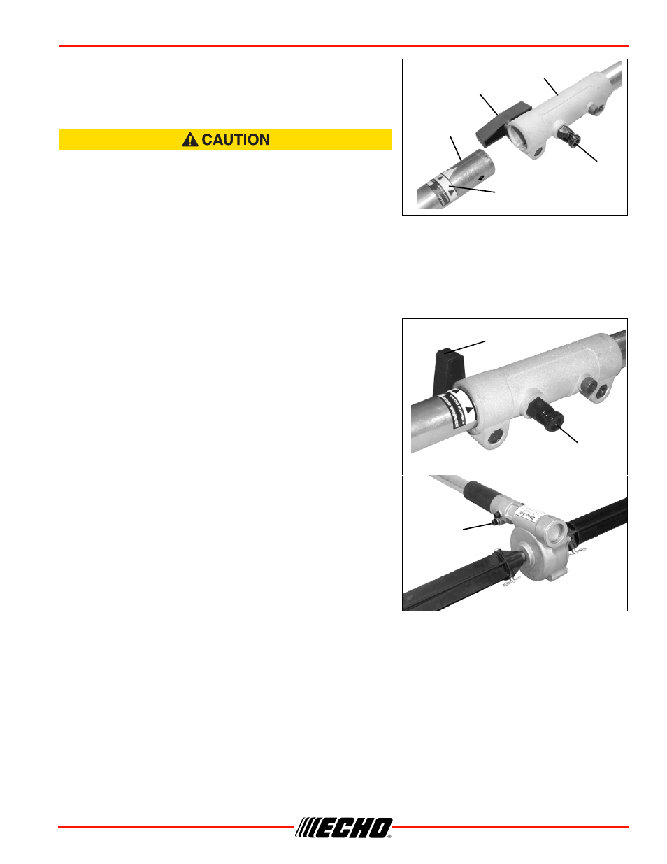
1. Set Power Head/Shaft Assembly on a level surface.
2. Pull locator pin (A) out, and turn counter-clockwise 1/4 turn
to lock-out position.
3. Remove vinyl cap from attachment drive shaft.
Thrown objects hazard. Install lower drive shaft so that gear
housing clamping bolt (F) faces downward. Otherwise debris
will be thrown toward users.
4. Remove cardboard spacer, if necessary.
5. Carefully fit attachment drive shaft assembly into coupler (B) to decal assembly line (C), making sure
that the inner lower drive shaft engages the square upper drive shaft socket.
Note: Earlier model Power Heads may have shorter couplings. Short couplings fit flush to decal point (E).
New couplings are 4-3/4 in. long, and fit flush to line (C).
Note: Lower bearing housing and head assembly must be in line with the engine.
6. Rotate locator pin (A) 1/4 turn clockwise to engage lower
shaft hole. Insure locator pin is fully engaged by twisting
lower drive shaft. Locator pin should snap flush in coupler.
Full engagement will prevent further shaft rotation.
7. Secure lower shaft assembly to coupler by tightening
clamping knob (D).
A
B
D
C
E
D
A
F