Warning – Echo 73454 Owners Manual v.3 User Manual
Page 20
4 INCH CHIPPER
18
ASSEMBLY
2.2 PTo model aSSemblY
2.2.1 aTTach chiPPer chuTe
use a support or hoist to hold the chipper chute in
place on the chipper frame
Mount the chute to the chipper housing using four 3/8"
x 1-1/2" bolts and locknuts.
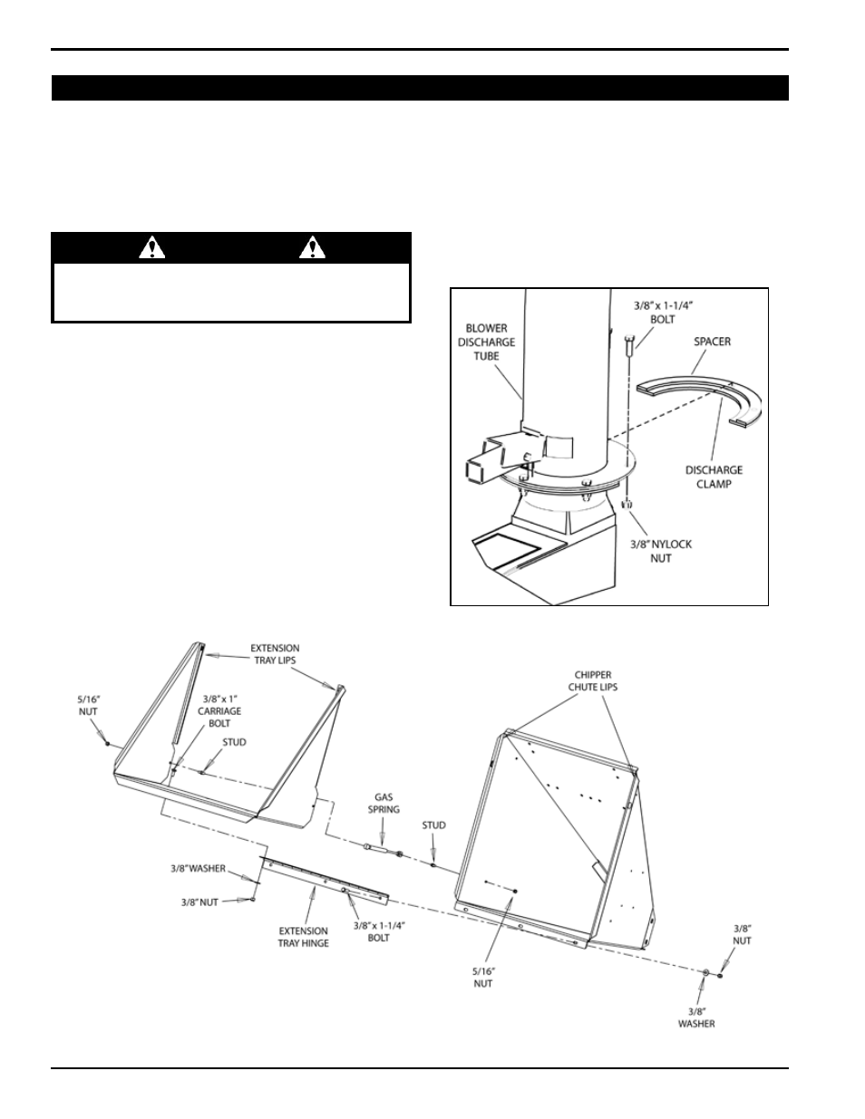
2.2.2 aTTach exTenSion TraY ("S" modelS)
attach the extension hinge to the chipper chute with
three 3/8" x 1-1/4" bolts, washers and nylock nuts.
Slide the chute extension tray over the chipper chute.
position the lip of the extension tray behind the lip
on the chipper chute (Figure 2.6). align the four bolt
holes in the chute extension tray with the bolt holes
in the hinge.
Insert four 3/8" x 1" carriage bolts through the tray and
the extension hinge. Secure the bolts with washers
and nuts.
Connect the gas spring to the side of the chipper chute
and extension tray with ball studs and 5/16" nylock nuts
as shown in Figure 2.6.
1.
2.
1.
2.
3.
4.
Warning
do not operate this unit without the chipper chute
correctly installed. Rotating cutting blades can cause
serious personal injury.
Figure 2.6, Attaching the extension tray ("S" models only)
2.2.3 aTTach bloWer diScharge Tube
Slide the blower tube discharge clamp underneath the
mounting flange on the chipper frame.
Install the second half of the spacer and clamp (in-
cluded in owner's kit) to the tube and flange with 3/8"
x 1-1/4" bolts and nylock nuts (Figure 2.7). Rotate the
tube 360 degrees to make sure it is mounted correctly.
lock it in place with the lock lever.
1.
2.
Figure 2.7, Chipper discharge assembly