3 attach discharge tube, 4 connect pto driveline, Important – Echo 74554 Owners Manual v.3 User Manual
Page 11
7
5 INCH CHIpper
ASSEMBLY
2.4.1 CHeCK lengTH of PTo driveline
Attach chipper to tractor with three-point hitch.
1.
you must make sure that the PTO driveline supplied
2.
with your machine is the appropriate length for your
tractor. Adjust the chipper up and down and measure
the shortest and longest distance between the chipper
rotor shaft and tractor PTO.
The PTO driveline has a
3.
maximum extension of
24.49" with a 6.43" overlap. If your longest distance
is greater than 24.49", contact your dealer to obtain
a longer PTO driveline.
The PTO driveline has a
4.
minimum compression of
18.1". If your shortest distance is less than this, cut
the driveline to fit as explained in section 2.4.2.
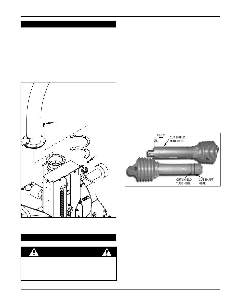
2.4.2 sHorTening a PTo driveline
Pull the driveline into two pieces. Connect one end to
1.
the tractor PTO and the other end to the chipper rotor
shaft. Line up the two halves parallel to each other.
Measure the distance from the end of one driveline
2.
tube to the bottom of the end shield of the other drive-
line half (dimension A in Fig. 2.4). Measure and mark
the driveline tube 1-9/16” inward from dimension A.
Cut the shield tube in the marked position.
3.
Using the cut piece of shield tube as your measure-
4.
ment, place the cut piece against the end of the shaft.
Mark and cut the shaft.
Using the cut piece of shield tube as your measure-
5.
ment, mark and cut the tube on the other half of the
driveline, and then the shaft.
File both shaft ends, and slide the two halves back
6.
together.
2.4.3 ConneCTing THe PTo driveline
When you have confirmed that the driveline is the
1.
correct length for your tractor, connect the driveline
to the chipper rotor shaft using key stock and two set
screws in the owner’s kit.
Connect the opposite end of the PTO shaft to the
2.
tractor.
1. Slide the blower discharge tube onto the mounting
flange on the chipper frame (see Figure 2.3). Half of
the mounting clamp is already attached to the tube.
2. Tighten the bolts to secure it.
3. Install the second half of the clamp to the tube and
flange. Secure it with (3) 1-1/4" bolts and nylock nuts.
4. grease the chute grease zerk to allow free rotation.
Rotate the tube 360 degrees and lock it in place with
the handle to make sure it is mounted correctly.
2.3 aTTaCH disCHarge Tube
2.4 ConneCT PTo driveline
Figure 2.3 Attach discharge tube
Figure 2.4 Shorten the driveline if it is too long
5/16 x 1”
BOLT
5/16 x 1-3/4”
BOLT
5/16”
NYLOCK
NUT
DEFLECTOR
KNOB
3/8 X 1-1/4”
HEX BOLT
3/8”
NYLOCK
NUT
imPorTanT
The tractor must have a
•
standard 540 rPm PTo
shaft.
If the tractor has an electric PTO clutch, consult your
•
dealer for correct operating procedures.