6 raise/lower access cover, 7 feed roller speed control, 8 chipper feed controller – Echo CH8720iH Owners Manual v.1 User Manual
Page 18: 9 feed roller control bar
14
8 INCH TURNTABLE CHIPPER
OPERATION
4.6 raise/lower access cover
1. Rotate the discharge chute so it is parallel to the access
cover.
2. Remove the two 3/8 x 1-1/4" bolts, nuts and washers
securing the access cover to the chipper housing.
3. After lowering the access cover, secure the access
cover to the chipper housing using two 3/8 x 1-14" bolts,
nuts and washers.
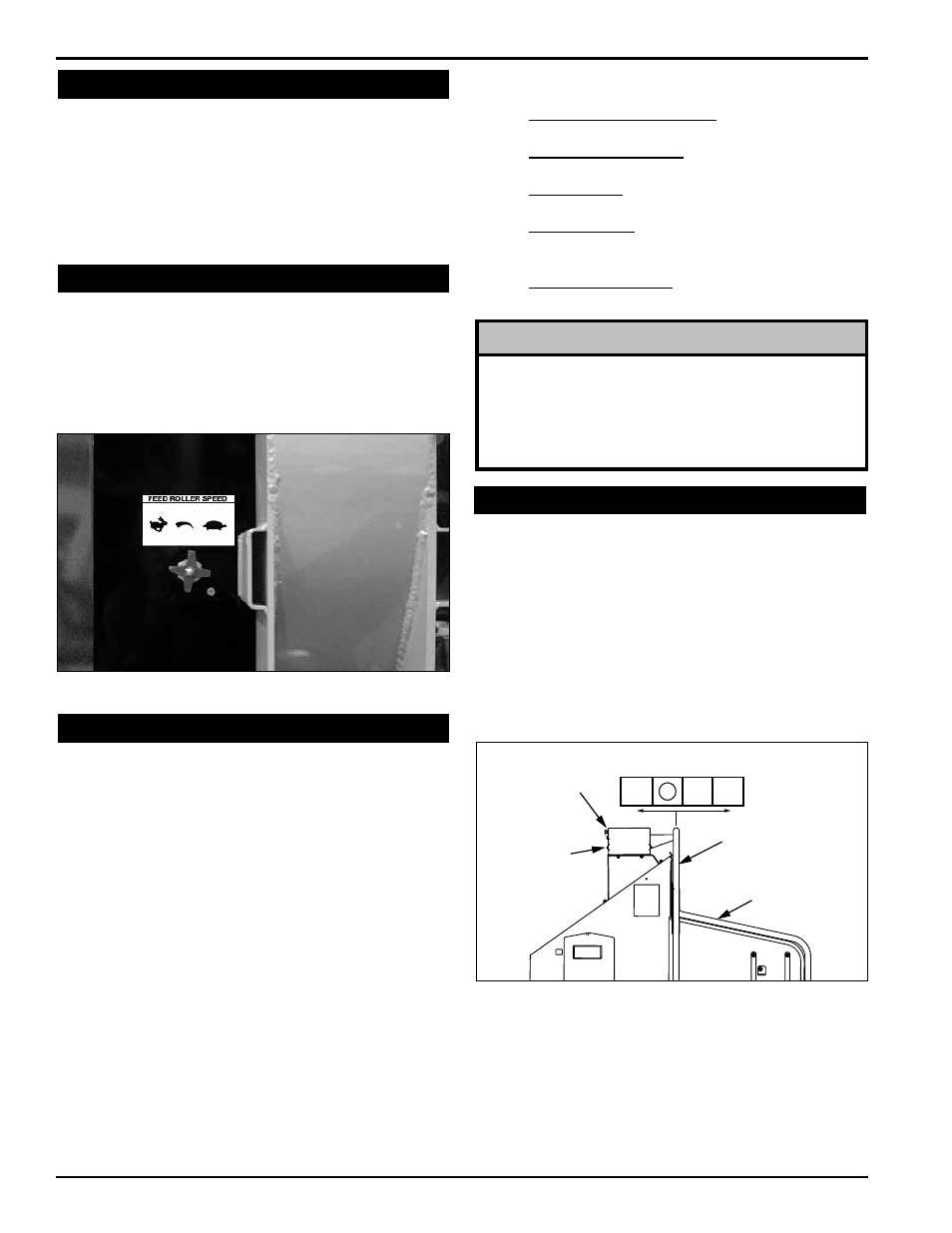
The feed roller speed control is used to control the speed
of the feed roller allowing the operator to have better con-
trol of material being fed into the chipper.
For optimum chipping, it is recommended that the feed
roller operate at a faster rate for smaller branches and at
a slower rate for larger branches.
4.7 FeeD roller sPeeD conTrol
Figure 4.2 - Feed Roller Speed Control.
4.8 chiPPer FeeD conTroller
4.9 FeeD roller conTrol Bar
noTe
The disk sensor and feed roller control bar sensors
must be set to the correct clearance or the chipper will
not operate. Set the clearance to 1/32” (the width of a
credit card). The sensor will flash with every rotation of
the chipper disk when the clearance is set correctly.
R
REVERSE
R
F
FORWARD
STOP
REVERSE
RESET/OVERRIDE
BUTTON (WHERE
AVAILABLE)
CONTROLLER
LIGHT
FEED ROLLER
CONTROL BAR
SAFETY BAR
(WHERE
AVAILABLE)
This machine is equipped with a Plus 1 Controller. The
controller monitors the chipper disk RPM and regulates
the feed roller.
when chipper disk rPm drops too low, the feed roller
is stopped automatically to allow the chipper disk to
process material.
when the chipper disk returns to chipping rPm, the
feed roller will automatically reengage.
Try again Feature: If the feed roller becomes obstructed,
the controller will reverse the feed roller momentarily
to clear the obstruction. The controller will then engage
the feed roller and feed the material again.
if this cycle continues, remove or reposition the material
manually.
remember to sharpen blades frequently so material
will feed smoothly.
The controller light will flash the following codes (see
sec. 6 for more information):
•
Normal Operating RPM: Steady green light
indicates engine has reached full RPM.
•
Feed Bar Not in STOP: Flashing red light indicates
operator must put feed bar in STOP position.
•
Service Code: Flashing amber light is a reminder
to check blade sharpness.
•
RPM Too low: Flashing green light indicates
operator must increase engine RPM before starting
to chip.
•
Safety Bar Activated: Steady red light (CE
Compliant models only).
The Feed roller control Bar is used to manually control
the direction of the feed roller rotation.
• Move the feed roller control bar to FORWARD (F)
when you want the materials to feed into the chipper.
The controller light must be steady green.
• Move the feed roller bar to REVERSE (R) when you
want the chipper push materials back out of the feed
chute.
• Move the feed roller bar to STOP to halt the rotation
of the feed roller.
ce comPlianT moDels onlY
Push the safety Bar in the event of an emergency and
forward feed will stop. Push the reset/override button to
resume forward feed after returning the safety bar to its
normal operating position.
upon start-up, the controller light will glow a steady red.
Push the reset/override button to reset.
if false trips occur, the reset button can be held in for 5
seconds to override the system.