Warning, 6 trailer 5.5 plugged disk, 7 drive belts – Echo 76824 Owners Manual v.3 User Manual
Page 21
17
TURNTABLE CHIPPER
SERVICE & MAINTENANCE
BEFORE INSpECTINg OR SERvICINg ANy pART OF ThIS MAChINE, ShUT OFF pOWER SOURCE,
DISENgAgE ThE hyDRAULICS, OpEN ShIELD AND MAkE SURE ALL MOvINg pARTS hAvE COME TO A COMpLETE STOp.
Warning
Check wheel bolt torque every 8 hours of towing.
Check air pressure in tires every 8 hours of towing. Inflate
to pressure marked on sidewall of tire.
Check and repack wheel bearings with grease every 12
months.
When towing, use a the proper size trailer ball, and always
connect the safety chains. Make sure trailer hitch bolts are
tight and secure.
1.
2.
3.
4.
5.6 Trailer
5.5 Plugged disK
If the machine becomes plugged, lift the engagement handle,
shut off the engine, disconnect the spark plug wire and al-
low the machine to come to a complete stop before clearing
debris. Do not operate the machine without proper guards
and shields in place.
Warning
Feeding too large or too much material at once may plug the
chipper. To clear a plugged disk, proceed as follows:
Lift the engagement handle and turn off engine key switch.
Allow all moving parts to come to a complete stop.
Remove the two 3/8" retaining bolts holding the access cover
to the chipper frame and lift up access cover.
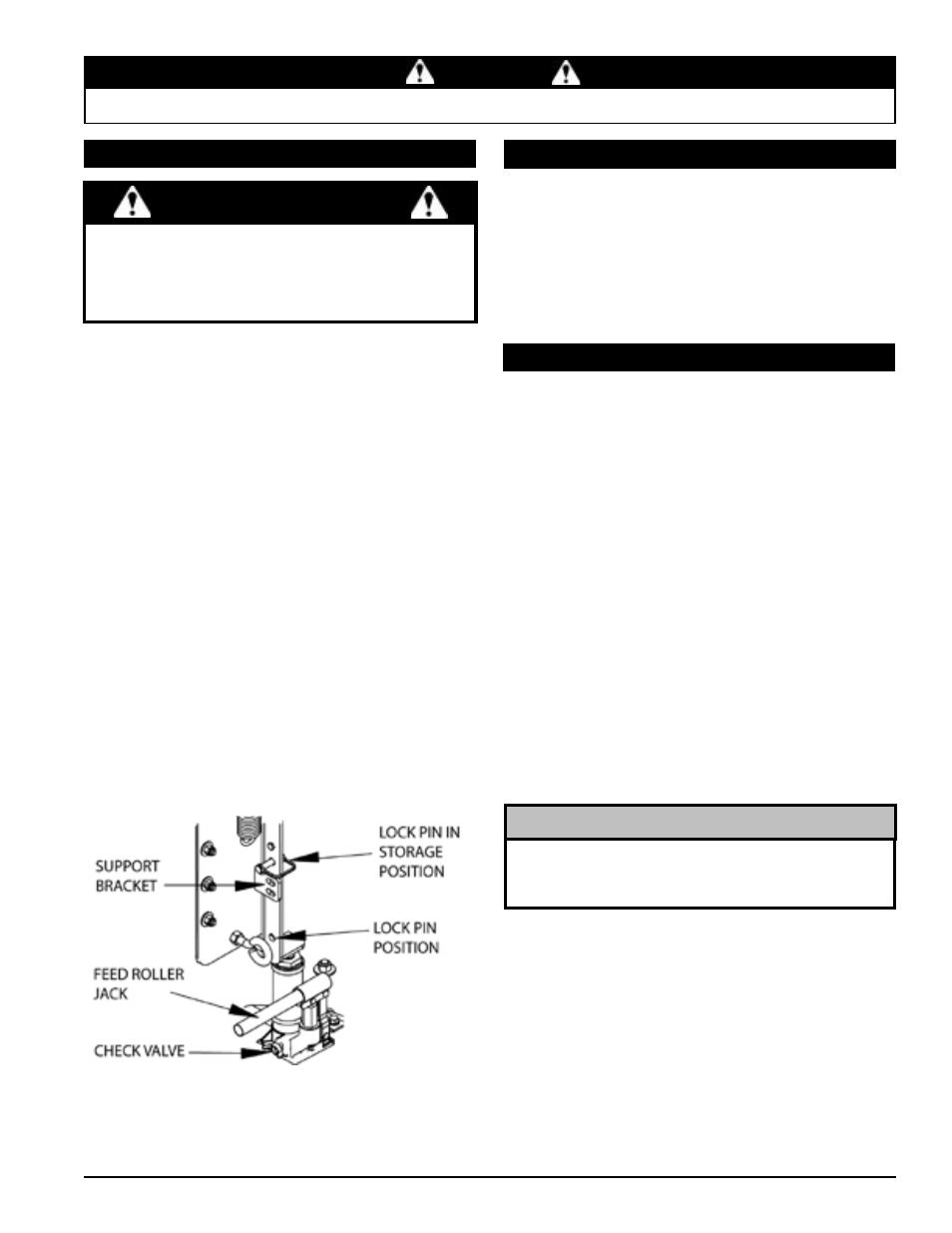
Remove the lock pin from storage position (see below).
Turn check valve clockwise to engage the jack pump.
pump the handle to raise the feed roller until the lock pin
position aligns with one of the support bracket holes.
Secure the position by putting the lock pin through the sup-
port bracket and lock pin position.
Clean the debris away from the chipper disk. Turn the disk
by hand to be sure it is free to rotate. Be careful to avoid the
chipper blades when cleaning out the debris.
Remove the lock pin and put it back in storage position.
LEAvINg ThE LOCk pIN IN ANy OThER pOSITION MAy
INTERFERE WITh FEED ROLLER OpERATION.
Turn the check valve counterclockwise to disengage the
pump and lower the jack.
Close access cover and replace bolts.
Start the engine. Lower the engagement handle when en-
gine is running to engage drive belt. Resume operation at
1/4 throttle.
1.
2.
3.
4.
5.
6.
7.
8.
9.
10.
11.
Figure 5.5 - Feed Roller Jack
5.7 drive belTs
5.7.1 rePlacing disK drive belT
Check the condition of the drive belt annually or after every 25
hours of operation, whichever comes first. If the belt is cracked,
frayed, worn or stretched, replace it. Replace belt with original
banded type belt only. Do not use single type belts.
Lift engagement handle to disengage drive belt.
Loosen bolt on engine tie. DO NOT REMOvE.
loosen the bolts securing the belt kicker to the engine (lo-
cated above the small sheave). do NoT RemoVe.
Assure the belt tensioning bolts on the engine mount plate
are tight against the engine mount.
Turn each of the two bolts eight revolutions counterclock-
wise.
Loosen the four engine mount bolts and slide engine towards
chipper housing.
Remove the large idler pulley.
Using a wrench, pull the small idler pulley away from the
hydraulic belt to release the tension.
Remove the hydraulic drive belt from the drive pulley on
the engine.
Remove the old disk drive belt and install new disk drive belt
on engine and large pulley.
Install large idler pulley
Lower engagement handle to engage drive belt
Alternately turn each of the belt tension bolts clockwise an
equal number of turns until the belt deflection at the center
of the belt is 7/16” when a 20 lb load is placed against the
belt (Figure 5.5).
Check pulley alignment using a straight edge and adjust the
appropriate belt tension screw if required.
Tighten the four engine mount bolts to the appropriate
torque.
1.
2.
3.
4.
5.
6.
7.
8.
9.
10.
11.
12.
13.
14.
15.
If belt does not easily install, turn the two belt tension bolts
counterclockwise an equal number of turns and slide engine
closer to chipper until belt can be installed.
noTe