Wiring schematic, Electrical installation – Echo 72825 Instruction User Manual
Page 3
Instruction Sheet
MODELS: Ch911Dh (72928), 72942 &
Ch922Dh (74950)
Crimp a ring terminal onto the Black, ground lead.
1.
Drill a 3/16” hole in the trailer, close to the solenoid
2.
valve, and secure the ground wire with the #10 self-
tapping screw provided.
Connect the two-pin connector to the top of the valve
3.
coil.
Crimp a ring terminal to the Red wire in the Feed Sen-
4.
sor harness and attach to “B” terminal on the back of
the Murphy Switch.
Connect the socket connector to the LOFA control.
5.
Secure wiring harness with cable ties as appropriate.
6.
ELECTrICAL InSTALLATIOn
MODELS: Ch6614h (72620), 74824 & 72825
note: For Models Ch6614h (72620) & 74824 (honda En-
gines), note STEP 4 and refer to the wiring schematic.
Crimp a ring terminal onto the Black ground lead.
1.
Drill a 3/16” hole in the trailer, close to the solenoid
2.
valve, and secure the ground wire with the #10 self-
tapping screw provided.
Connect the two-pin connector to the top of the valve
3.
coil.
Crimp a spade connector onto the Red wire in the
4.
Feed Sensor harness and connect to the yellow wire
from the Kohler engine harness. For Honda engines,
the Red wire is attached to the black wire with a yellow
tracer coming from the engine.
Connect the socket connector to the LOFA control.
5.
Secure wiring harness with cable ties as appropriate.
6.
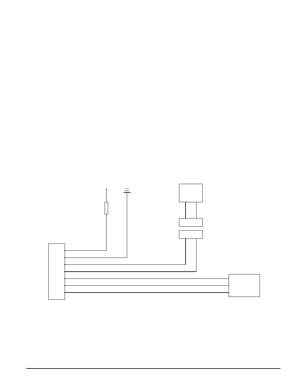
WIRING SCHEMATIC
5
6
4
2
3
1
WIRE COLOR CODE LEGEND
O ORANGE
G GREEN
B BLACK
R RED
BL BLUE
BR BROWN
B
O
G
BR
B
PROXIMITY
SENSOR
B
BL
BR
7
BL
R
FUSE
8 AMP
R
POWER GROUND
B
COIL
CONN
CONN
O
G