6 cylinder removal and installation, Main boom telescope cylinder removal, Cylinder removal and installation -10 – JLG 740AJ Service Manual User Manual
Page 296: Main boom telescope cylinder removal -10, Components main boom and tower boom -10, Holding valve torque specifications -10
SECTION 5 - HYDRAULICS
5-10
– JLG Lift –
3121160
5.6 CYLINDER REMOVAL AND
INSTALLATION
Main Boom Telescope Cylinder Removal
1. Place machine on a flat and level surface, with main
boom in the horizontal position. Extend telescope
up to gain access to main fly boom telescope cylin-
der, rod end pin #1.
2. Shut down engine. Support main boom platform
end with a crane of adequate capacity.
HYDRAULIC LINES AND PORTS SHOULD BE CAPPED IMMEDIATELY
AFTER DISCONNECTING LINES TO AVOID THE ENTRY OF CONTAMI-
NANTS INTO THE SYSTEM
3. Tag and disconnect hydraulic lines to telescope cyl-
inder. Use suitable container to retain any residual
hydraulic fluid. Cap hydraulic lines and ports.
4. Remove the retaining rings that retain the telescope
cylinder rod to the fly boom.
5. Using a suitable brass drift, carefully drive telescope
cylinder rod pin from the fly boom.
Table 5-2. Holding Valve Torque Specifications
HOLDING VALVE TORQUE SPECIFICATIONS
Description
Torque Value
SUN - 7/8 hEX m20 X 1.5 this.
30-35 ft. lbs.
(41 - 48 Nm)
SUN - 1 1/8 HEX 1 - 14 UNS THDS.
45 - 50 ft. lbs.
(61 - 68 Nm)
SUN - 1 1/4 HEX m36 X 2 THDS.
150 - 160 ft. lbs.
(204 - 217 Nm)
RACINE - 1 1/8 HEX 1 1/16- 12 THDS.
50 - 55 ft. lbs.
(68 - 75 Nm)
RACINE - 1 3/8 HEX 1 3/16- 12 THDS.
75 -80 ft. lbs.
(102 -109 Nm)
RACINE - 1 7/8 HEX 1 5/8- 12 THDS.
100-110 ft. lbs.
(136 - 149 Nm)
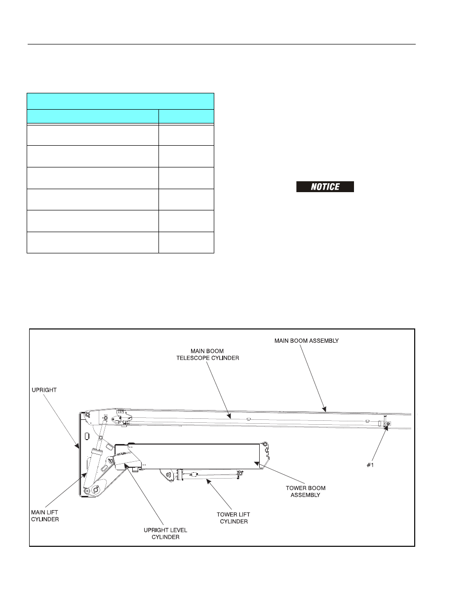
Figure 5-13. Components Main Boom and Tower Boom