6 upright, Removal, Upright level cylinder removal – JLG 740AJ Service Manual User Manual
Page 230: 7 tower boom assembly, Upright -14, Removal -14 upright level cylinder removal -14, Tower boom assembly -14, Removal -14, Location of components - upright -14, 6 upright removal
SECTION 4 - BOOM & PLATFORM
4-14
– JLG Lift –
3121160
4.6 UPRIGHT
Removal
HYDRAULIC LINES AND PORTS SHOULD BE CAPPED IMMEDI-
ATELY AFTER DISCONNECTING LINES TO AVOID ENTRY OF CON-
TAMINANTS INTO SYSTEM.
1. Remove the main boom.
2. Tag and disconnect hydraulic lines to (upper) main
lift cylinder. Use a suitable container to collect any
residual hydraulic fluid. Cap hydraulic lines and
ports.
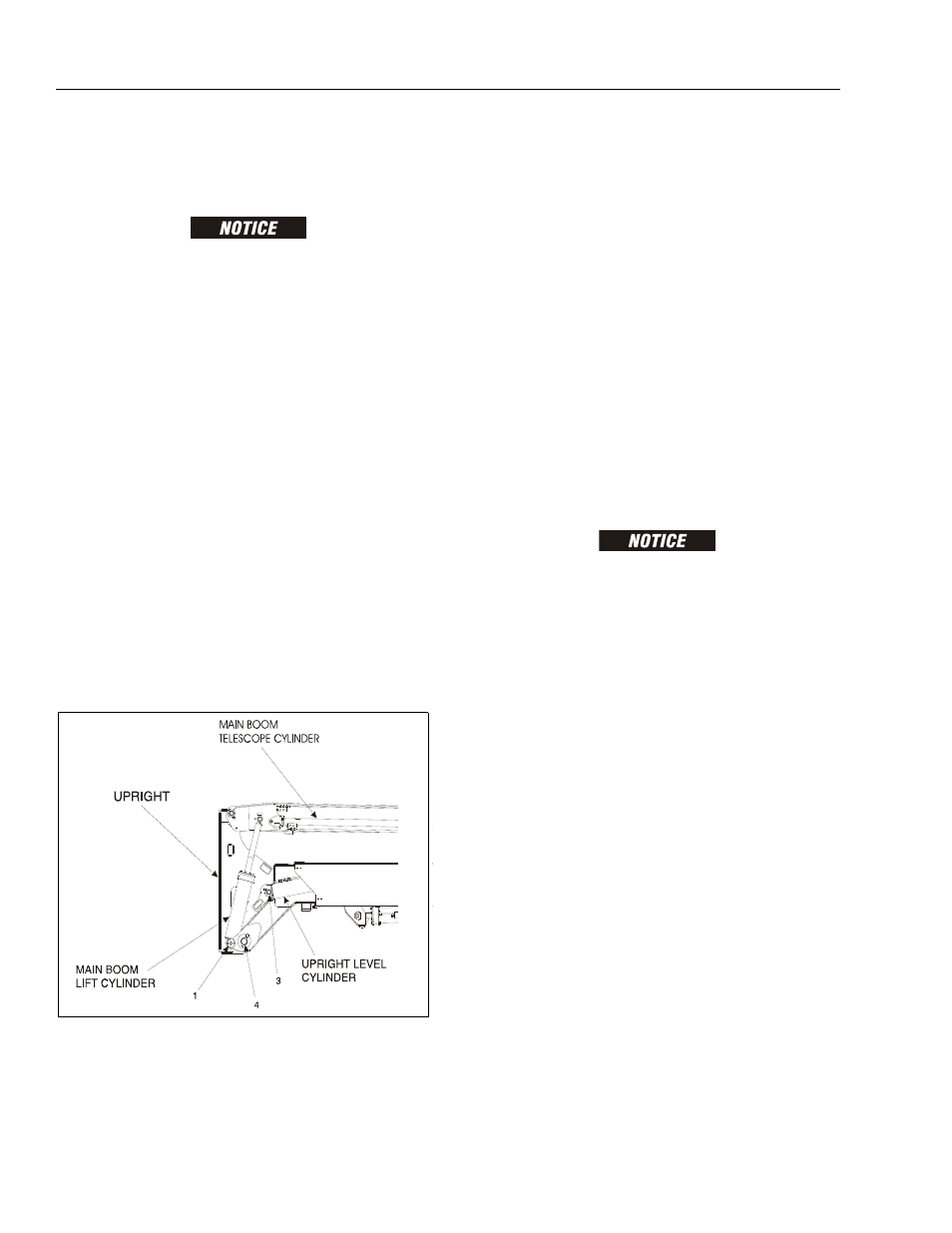
3. Remove mounting hardware from Main lift Cylinder
barrel end. Using a suitable brass drift and hammer,
remove pin #1 from Upright and remove Main Lift
Cylinder.
4. Disconnect wiring harness to horizontal limit switch.
5. Upright Level Cylinder Removal.
a. Using a suitable lifting device, support the
Upright.
b. Remove mounting hardware securing hose
bracket in upright, and remove the hose bracket.
c. Remove mounting hardware from the upright
level cylinder. Using a suitable brass drift and
hammer, remove pin #3 from upright.
d. Remove Upright Level Cylinder from upright
6. Remove mounting hardware from the Upright Pivot
Pin using a suitable brass drift and hammer. Remove
pin # 4 from tower boom assembly.
Upright Level Cylinder Removal
1. With upright removed, override tower telescope limit
switch and extend the tower boom to gain access to
the upright level cylinder barrel end attach pin.
2. Tag and disconnect hydraulic lines to the upright lift
cylinder. Use a suitable container to collect any
residual hydraulic fluid. Cap hydraulic lines and
ports.
3. Using an overhead crane or suitable lifting device,
support the upright lift cylinder, remove mounting
hardware from the barrel end of the upright lift cylin-
der and remove the pin.
4. Carefully remove the upright lift cylinder and place
on a suitable work surface.
4.7 TOWER BOOM ASSEMBLY
Removal
HYDRAULIC LINES AND PORTS SHOULD BE CAPPED IMMEDI-
ATELY AFTER DISCONNECTING LINES TO AVOID ENTRY OF CON-
TAMINANTS INTO SYSTEM.
1. Using an overhead crane or suitable lifting device,
support the entire Tower Boom Assembly and sepa-
rately support the tower lift cylinder.
2. Remove mounting hardware from tower lift cylinder
rod end. with a brass drift and hammer, remove the
tower Lift cylinder Pin disconnecting the tower lift
cylinder.
3. Remove mounting hardware from the upright level-
ing cylinder rod end. with a brass drift and hammer,
remove the pin, disconnecting the upright cylinder.
Remove with suitable lifting device.
4. Remove mounting hardware from the tower boom
pivot pin. Using a suitable brass drift and hammer,
remove pin #2 from turntable assembly.
5. Using all applicable safety precautions, carefully lift
the Tower Boom Assembly clear of turntable and
lower to ground or a suitable supported work sur-
face.
Figure 4-5. Location of Components - Upright