8 mast assembly and disassembly procedures, Mast disassembly procedure, 8 mast assembly and disassembly procedures -20 – JLG 41AM (3120872) Service Manual User Manual
Page 42: Mast disassembly procedure -20, Mast section - assembly/disassembly reference -20, Am series mast component features -20
SECTION 2 - SERVICE PROCEDURES
2-20
– JLG Lift –
3120872
2.8 MAST ASSEMBLY AND DISASSEMBLY
PROCEDURES
The AM Series personnel lift mast sections are contructed
of extruded aluminum, protected with an anodized surface
finish. The mast sections rails are interlocked into each
other when assembled and are guided by slide pads
mounted at the top and bottom of the rails on both sides
of the mast section.
The current AM model line mast assemblies have been
designed with either five (5), six (6) or seven (7) mast sec-
tions as shown following;
Assembly procedures for all mast assemblies is basically
the same, carefully slide the mast sections together from
bottom until mast ends are even, (when sliding mast sec-
tions together be careful not to scratch the anodized sur-
face in the slide pad channels). Assemble the hardware to
the bottom of mast section first, then slide this section out
the top of previous section and assemble hardware to the
top of mast, (See Figure 2-2.). Always install slide pad
shims with slide pads inserted into the slide pad channels,
(ends of mast sections even).
Mast Disassembly Procedure
NOTE: Reference to mast sections-5/-6/-7 made following is
dependent on which model machine you are servic-
ing since the 20 ft. machines use five (5) mast sec-
tions, the 25 and 36 ft. models use six (6) mast
sections, the 30 and 41 ft. models use seven (7)
mast sections .
1. After the platform and other hardware have been
removed from the mast, and mast has been
removed from machine, lay mast assembly down
with the shortest mast section-5/-6/-7 on top and fac-
ing up.
2. Remove sequencing retract cables from sides of
mast assembly and the mini covers from the top of
each mast section. Also, remove the latch bar
assembly from BOTTOM of mast section-5/-6/-7.
Table 2-4. AM Series Mast Component Features
Model
No. of Mast
Sections
Extend Device
20AM
5
Chains
25AM / 36AM
6
Chains
30AM / 41AM
7
Chains
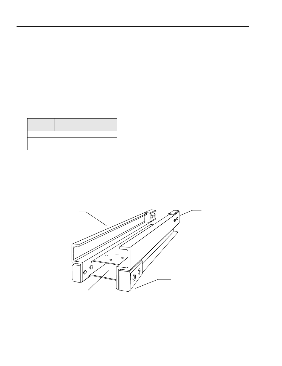
Figure 2-2. Mast Section - Assembly/Disassembly Reference.
TOP
(REFERSTOTOPEND
OFMAST SECTION-
ENDWITHCOVER
ANDSHEAVEWHEELS
ATTACHED)
BOTTOM
(REFERSTOBOTTOM END
OFMAST SECTION-
ENDWHICHSETSAT
MACHINESBASEFRAME)
CLOSEDRAIL
(REFERSTOCLOSEDRAIL
BACKOFMAST SECTION)
OPENRAIL
(REFERSTOOPENRAIL
FRONT OFMAST SECTION)