6 hydraulic pressure adjustment, 7 cylinder specifications, 8 serial number locations – JLG 41AM (3120872) Service Manual User Manual
Page 13: Hydraulic pressure setting -3, Cylinder specifications -3
SECTION 1 - SPECIFICATIONS
3120872
– JLG Lift –
1-3
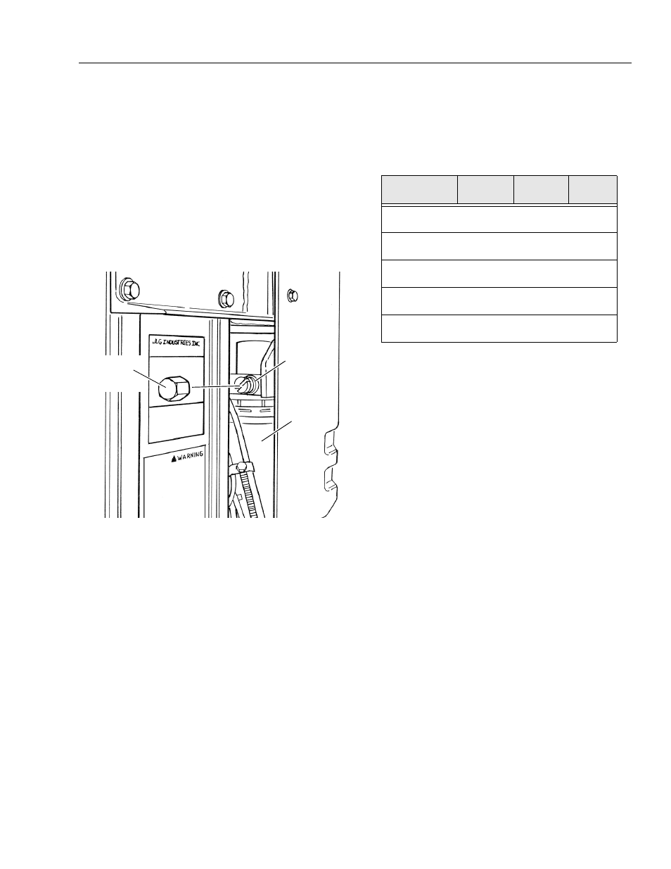
1.6 HYDRAULIC PRESSURE ADJUSTMENT
Adjust system pressure so that platform will raise with
rated capacity in platform.
Turning adjustment screw clockwise, increases system
pressure, turning screw counterclockwise, decreases
system pressure.
Do not adjust system pressure higher than required to
raise the load. Make pressure adjustment with oil at nor-
mal operating temperature. If pressure is set when oil is
cold, platform may not raise rated load after oil has
warmed.
1.7 CYLINDER SPECIFICATIONS
NOTE: All dimensions are given in centimeters cm, with the
equivalent, inches (in.), given in parentheses.
1.8 SERIAL NUMBER LOCATIONS
For machine identification, a serial number plate is affixed
to the machine. The plate is located on the back of the
mast, just above the mast support bracket. In addition,
should the serial number plate be damaged or missing,
the machine serial is stamped on the mast and on the
base frame.
Figure 1-1. Hydraulic Pressure Setting - Adjustment
Screw Located at Base of Pump Motor
(Remove Hex Head Cap as Shown)
PRESSURE
ADJUSTMENT
SCREW
HYDRAULIC
OILTANK
GROUND
CONTROL
STATION
COVER
ADJUSTMENT
SCREWCAP
(SHOWNREMOVED)
Table 1-3. Cylinder Specifications
DESCRIPTION
BORE
cm/(in.)
STROKE
cm/(in.)
ROD DIA.
cm/(in.)
Lift Cylinder -
20AM-AC & DC
4.14
(1.63)
143.50
(56.50)
3.50
(1.38)
Lift Cylinder -
25AM-AC & DC
4.14
(1.63)
143.50
(56.50)
3.50
(1.38)
Lift Cylinder -
30AM-AC & DC
4.14
(1.63)
143.50
(56.50)
3.50
(1.38)
Lift Cylinder -
36AM-AC & DC
4.14
(1.63)
211.40
(83.25)
3.50
(1.38)
Lift Cylinder -
41AM-AC & DC
4.14
(1.63)
198.75
(78.25)
3.50
(1.38)