JLG 41AM (3120872) Service Manual User Manual
Page 41
SECTION 2 - SERVICE PROCEDURES
3120872
– JLG Lift –
2-19
tom of the mast section-1. Shim to eliminate any
side clearance to prevent any strain on the sides of
the mast when the bolts are tightened.
7. New Design Cylinder Mount: Install the cylinder
mounting plates at the bottom of the mast section-1.
Mount plates two each side, using the the (2) two
long pass through bolts and nuts, apply Loctite
#242 to the bolt threads before tightening nuts.
8. Original Design Cylinder: Clamp the cylinder in the
mounting journal of the cylinder mount. Apply Loc-
tite #242 to the journal bolt threads and torque to 85
ft. lbs. Align the hole in the mounting journal with the
hole in the cylinder and Install the (1) 5/16" bolt.
New Design Cylinder: Install the mounting pin
through the side mounting brackets and the cylinder
valve body and through the mounting brackets on
the other side of the mast. Install the snap rings to
each end of the mounting pin.
9. Connect the hydraulic fittings and lines, (new fittings
should be used).
10. Slide the mast together (stowed position) from the
top of the mast.
11. Stand machine upright on it’s base wheels.
12. Connect the hydraulic line fittings at the pump.
13. Check oil level in the hydraulic oil reservoir, add oil
to fill line, if necessary.
14. Install the ground station (pump) cover.
15. Set-up machine for operation and cycle mast (up
and down) approximately 3 ft. to 4 ft. a few times.
16. Check the hydraulic oil reservoir again, add oil to the
fill line.
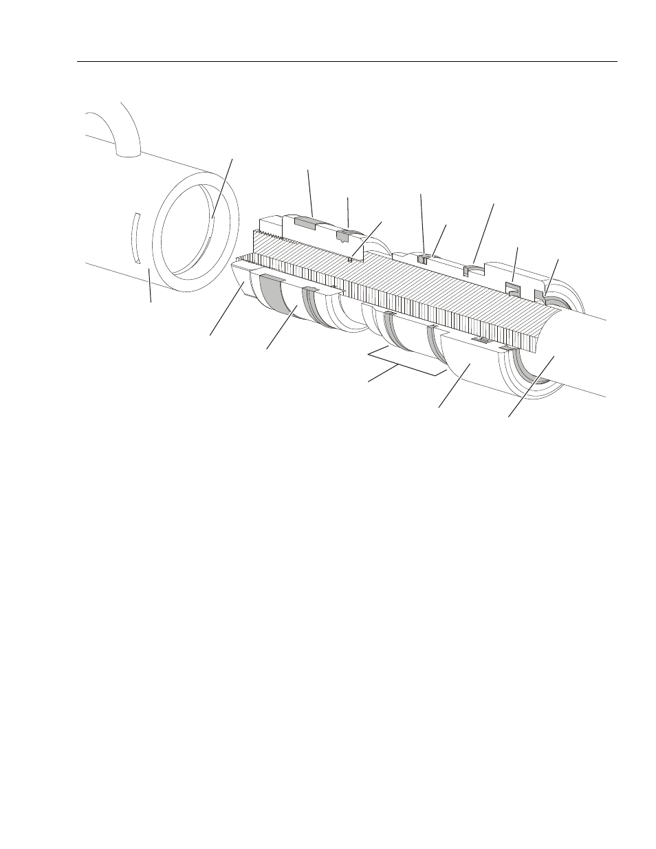
Figure 2-1. Lift Cylinder Internal Component Assembly Cross-Section.
PISTON
LOCKNUT
(Torque
175-200 Ft. Lb.)
WEAR
RING
PISTON
SEAL
O-RING
O-RING
BACKUP
RING
CYLINDER
HEAD
RETAINING
RING
RETAINING RING
GROOVE
ROD
SEAL
ROD
WIPER
CYLINDER
HEAD
WHEN ASSEMBLING
CYLINDER
APPLY ANTI-SEIZE
COMPOUND
AROUND THE HEAD
IN THIS AREA ONLY
CYLINDER
TUBE
ASSEMBLY
CYLINDER
ROD