JLG 450AJ ANSI Service Manual User Manual
Page 92
SECTION 2 - PROCEDURES
2-74
– JLG Lift –
3120749
a. Ignition module series: AA, AB and FA prior to
date code-1889 may need replaced. (refer to:
Ford Technical Bulletin # FF-91-99)
b. Check the vacuum advance tube attached to the
ignition module for secure connection.
Try to start the engine.
2.31 CHECKING THE FUEL
The engine may not be getting fuel to the carburetor
1.
Check the fuel shutoff solenoid
a. Must have 12 volt while cranking the engine.
2.
Check the electric fuel pump
a. Must have 12 volts or be able to hear the pump
running while cranking the engine.
b. Check fuel pressure, must have a minimum of
2-4lbs.
3.
Check Fuel Filter:
NOTE: Some JLG machines have a fuel return line between
the fuel pump and carburetor, if this return line is
pinched and the fuel pressure increases this indi-
cates a clogged fuel filter.
4.
Check the fuel pump supply line for any obstruction.
Try to start the engine.
NOTE: JLG Industries Inc. recommends the use of engine
block heaters and or cold weather packages for
machines intended for use in 0° F (-18° C) or colder
conditions. Refer to the JLG Parts Manual for specify
options for your machine.
(Machines equipped with non-hydrostatic gear pump
or non-proportional drive systems, i.e. H models,
60HA should consider having block heaters and or
cold weather packages installed for use in 20° F (-
6.5° C) and colder conditions.
2.32 TILT ALARM SWITCH
PERFORM TILT ALARM SWITCH LEVELING PROCEDURE A MINI-
MUM OF EVERY SIX MONTHS TO ENSURE PROPER OPERATION
AND ADJUSTMENT OF SWITCH.
Manual Adjustment
1.
Park the machine on a flat, level surface. Ensure
machine is level and tires are filled to rated pressure.
NOTE: Ensure switch mounting bracket is level and securely
attached.
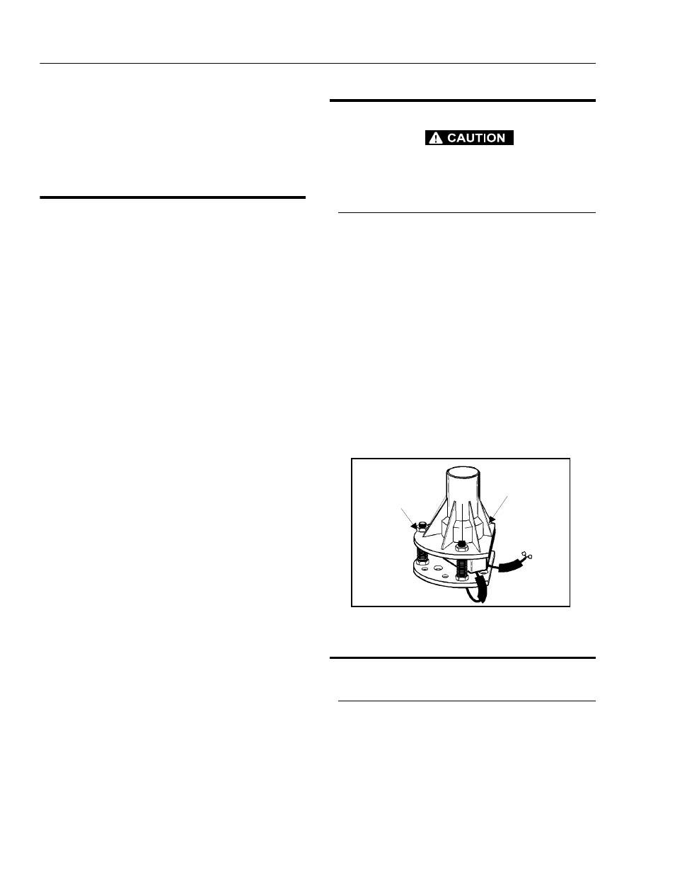
2.
Level the base of the indicator by tightening the
three flange nuts through approximately one quarter
of its spring travel. DO NOT ADJUST THE "X" NUT
DURING THE REMAINDER OF THE PROCEDURE.
3.
With the electrical connections complete, using bub-
ble level on top of indicator, slowly tighten or loosen
the three flange nuts until indicator is level.
4.
Individually push down on one corner at a time;
there should be enough travel to cause the switch to
trip. If the switch does not trip in all three tests, the
flange nuts have been tightened too far. Loosen the
"X" nut and repeat steps (2). through (4).
2.33 PRESSURE SETTING PROCEDURES
Proportional Sequence Valve
1.
Install a pressure gauge at port G1 on the Main
Valve and start the engine.
2.
The gauge should read between 230 and 325 psi
(16 and 22.5 bar). This valve is non-adjustable.
X
Y
Y
Figure 2-41. Tilt Switch Adjustment