11 drive card setup procedures – JLG 660SJ Service Manual User Manual
Page 130
SECTION 4 - BOOM & PLATFORM
4-28
– JLG Lift –
3120840
3.
Install new seals (11), back-up ring (12), cap bearing
(13), bearing packing (14) and thrust ring (10) on
end cap (5).
4.
Place the actuator in the vertical position, install the
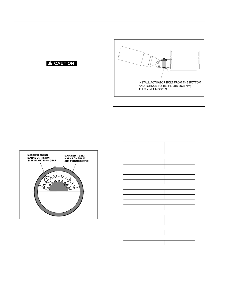
piston sleeve (3) in timed relation to the housing (1).
DO NOT MISALIGN THE SLEEVE TOO MUCH ANY ONE WAY, AS IT
WILL MARK THE CYLINDER BORE.
NOTE: The timing marks (the small punch marks on the
face of each gear), must be aligned for proper shaft
orientation. (See Actuator Timing.)
5.
Install the shaft (2) into housing (1) by aligning the
proper punched timing marks. (See Actuator Tim-
ing.)
6.
Temporarily tape the threaded portion of the shaft
will help installation past the shaft seals (masking
tape).
7.
The end cap (5) is torqued to 54 - 68 Nm, such that
the actuator begins rotation at approximately 6.9 Bar
pressure.
8.
The end cap must be secured against the shaft by
installing axial set screws (4).
4.11 DRIVE CARD SETUP PROCEDURES
NOTE: The following procedures are to be used as a begin-
ning basis for controller adjustment. After completing
the procedure, final adjustments are to be made
based on the machines function speed.
Figure 4-35. Actuator Timing
Table 4-1. Function Speeds
Function
Function Speed
In Seconds
Telescope
Extend
48-61
Retract
24-32
Lift
Up
46-60
Down
33-43
Articulating Jib Boom
Up
22-29
Down
16-22
Swing Speed
Full 360°
79-101
Platform Rotation
Left
22-30
Right
22-30
Drive Speed (2WD)
28-32 @ 200ft.
Drive Speed (4WD)
32-36 @ 200ft.