7 battery charging & maintenance, Battery maintenance and safety practices, Battery charger operation – JLG 20VP (3120848) Operator Manual User Manual
Page 17
SECTION 2 - PREPARATION AND INSPECTION
3120848
– JLG Lift –
2-5
2.7
BATTERY CHARGING & MAINTENANCE
VP Models are equipped with 24 volt, 10 amp output bat-
tery chargers (Europe - 240V AC input/50 Hz, U.K. Only -
120/240V AC input/50Hz, Australia - 250V AC input/50 Hz).
The battery charger includes a microprocessor controlled
automatic charge sensing circuit which can determine cell
voltage and regulate charger output as required. The
charger automatically terminates charging when a full bat-
tery charge is acheived. Also a built-in interlock device
prohibits driving the machine while the battery charger is
plugged in.
Battery Maintenance and Safety Practices
(Refer to Figure 2-2.)
ENSURE THAT BATTERY ACID DOES NOT COME INTO CONTACT
WITH SKIN OR CLOTHING. WEAR PROTECTIVE CLOTHING AND
EYEWEAR WHEN WORKING WITH BATTERIES. NEUTRALIZE ANY
BATTERY ACID SPILLS WITH BAKING SODA AND WATER.
BATTERY ACID RELEASES AN EXPLOSIVE GAS WHILE CHARG-
ING, ALLOW NO OPEN FLAMES, SPARKS OR LIGHTED TOBACCO
PRODUCTS IN THE AREA WHILE CHARGING BATTERIES.
CHARGE BATTERIES ONLY IN A WELL VENTILATED AREA.
ADD ONLY DISTILLED WATER TO BATTERIES. WHEN ADDING
DISTILLED WATER TO THE BATTERIES, A NON-METALLIC CON-
TAINER AND/OR FUNNEL MUST BE USED.
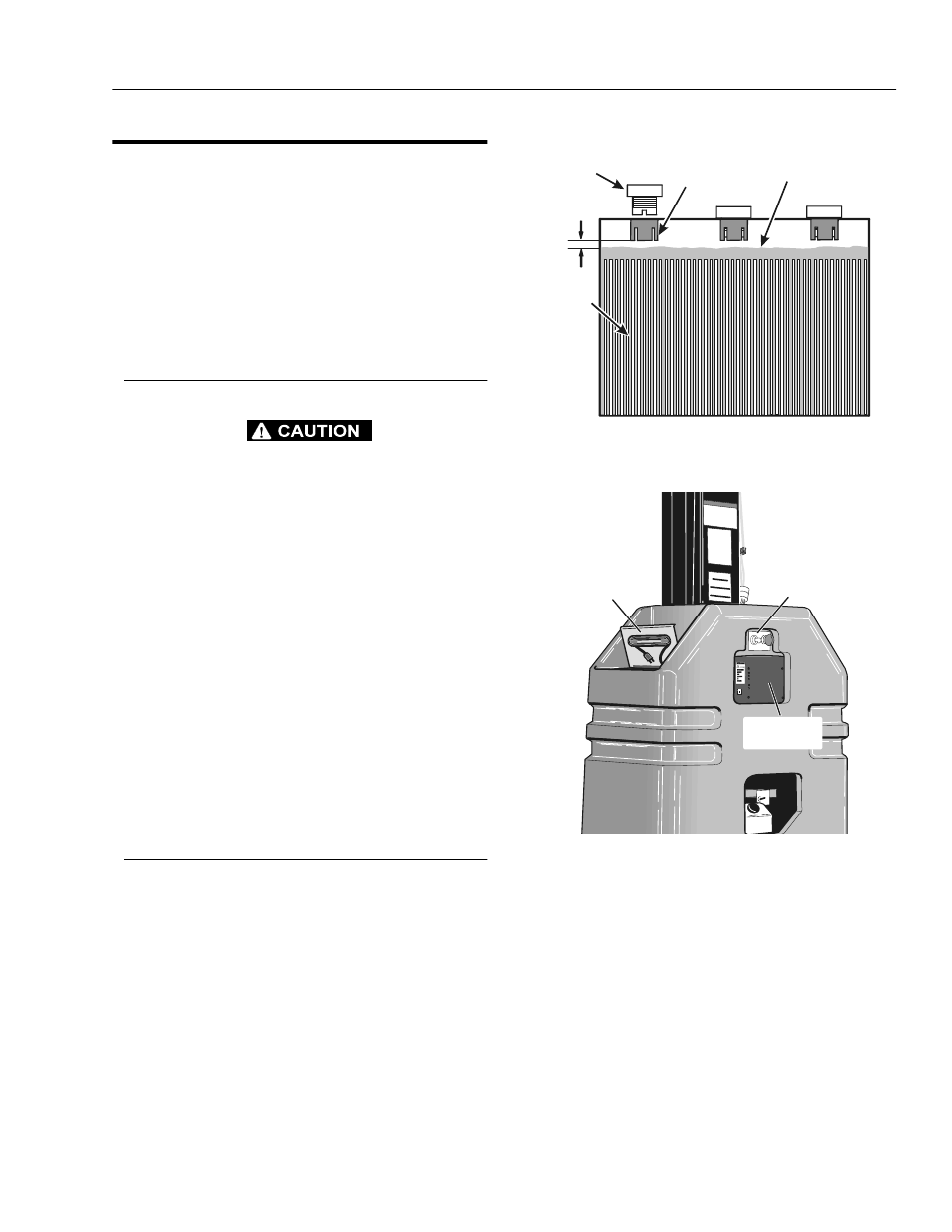
As with any wet cell battery, check the electrolyte level of
the batteries often, adding only distilled water when
required. When fully charged, battery fluid level should be
1/8" below vent tubes. (See Figure 2-2.).
• DO NOT fill to bottom of vent tubes.
• DO NOT allow fluid level to go below the top of the
plates when charging or operating.
Battery Charger Operation
(Refer to Figure 2-3 & 2-4.)
1.
Position machine in well ventilated area near an AC
electrical outlet and set the Ground Control-PLAT/
OFF/GRND key switch to the OFF position.
2.
Open the left battery cover and unwrap the battery
charger AC power cable from under the cover.
3.
Connect the battery charger AC power cable to a
properly grounded receptacle, use a suitable exten-
sion cord, if necessary.
4.
When powered on, the charger runs through a self-
diagnostic check which lights all five (5) lights on the
face of the charger three (3) times, then each light in
sequence, then all five (5) lights three (3) times
again on the front panel of the battery charger.
5.
When ready to charge, the CHARGER ON light and
the INCOMPLETE light on the front panel of the
charger will light up, the charger will then begin to
charge the batteries.
NOTE: If the ABNORMAL CYCLE light comes on and stays
on at any time during the charge cycle, see sub-sec-
tion following about the ABNORMAL CYCLE indica-
tor light.
Figure 2-2. Battery Fluid Level.
Figure 2-3. Charger Assembly and
Power Cord Storage.
1/8 "
BATTERY
FILLER CAP
FLUID LEVEL OF FULLY
CHARGED BATTERY
VENT TUBE
PLATES
KEY
SWITCH
CORD
STORAGE
AREA
BATTERY
CHARGER