Adjustment – JLG 450AJ Service Manual User Manual
Page 78
SECTION 2 - PROCEDURES
2-62
– JLG Lift –
3120869
Adjustment
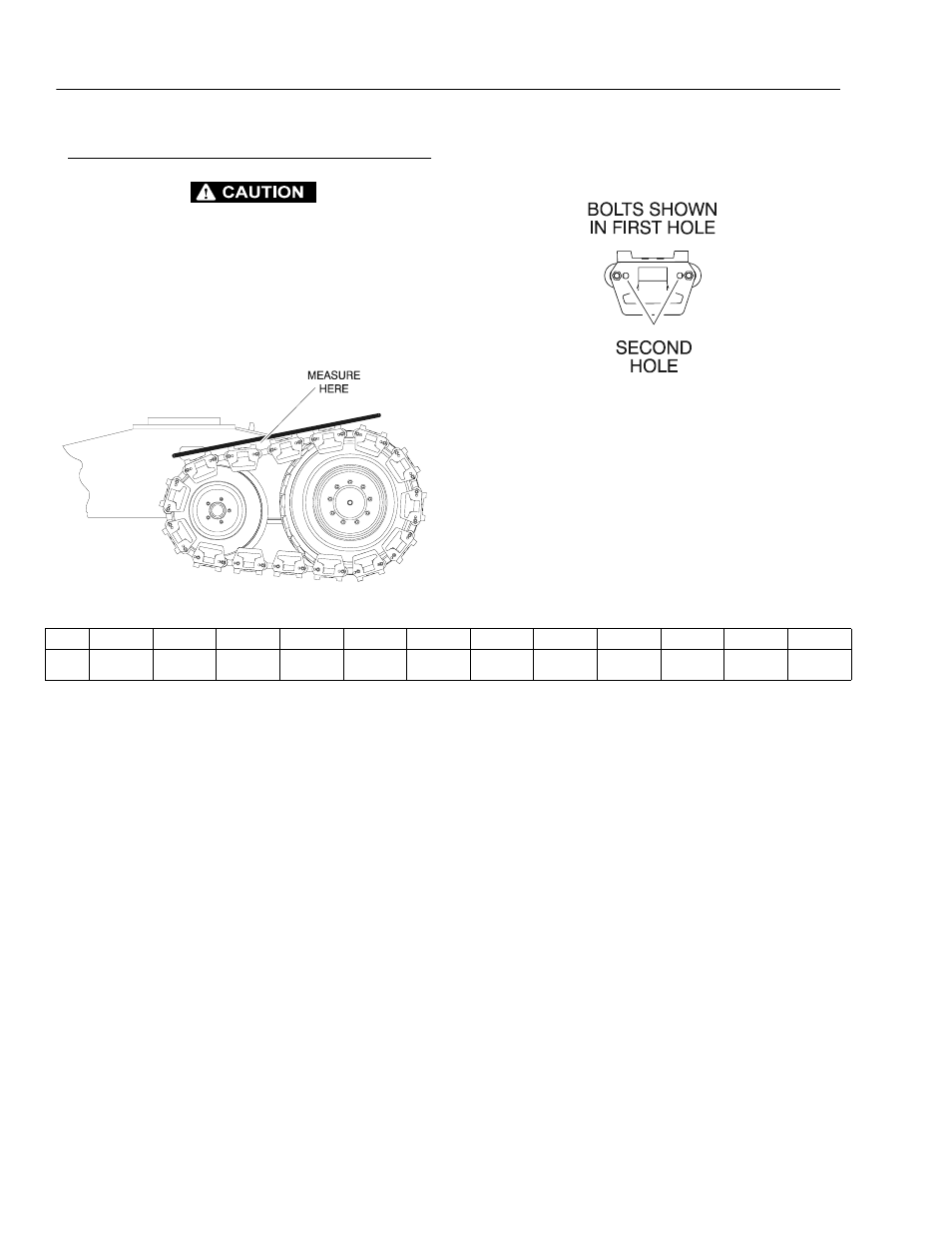
IMPROPER SLACK ADJUSTMENT COULD CAUSE TRACK PARTS
TO BREAK.
Place a straight edge long enough to reach from the idler
to the drive wheel on the tracks. Measure the maximum
amount of track sag from the high point of the track seg-
ment to the bottom of the straight edge. Properly adjusted
track will have approximately 1 to 2 inches (25 to 50 mm)
slack.
To adjust the slack measurement, move the bolts from the
first hole to the second to create more slack, or from the
second to the first to create less slack.
Table 2-5.Adjustment Chart
Move
1 Hole
2 Holes
3 Holes
4 Holes
5 Holes
6 Holes
7 Holes
8 Holes
9 Holes
10 Holes
11 Holes
12 Holes
Equals
0.81 in
(20.5 mm)
1.62 in
(41 mm)
2.43 in
(62 mm)
3.25 in
(82.5 mm)
4.06 in
(103 mm)
4.87 in
(124 mm)
5.68 in
(144 mm)
6.50 in
(165 mm)
7.31 in
(186 mm)
8.12 in
(206 mm)
8.93 in
(227 mm)
9.75 in
(248 mm)
Updated 2-16-00