JLG 450AJ Service Manual User Manual
Page 38
SECTION 2 - PROCEDURES
2-22
– JLG Lift –
3120869
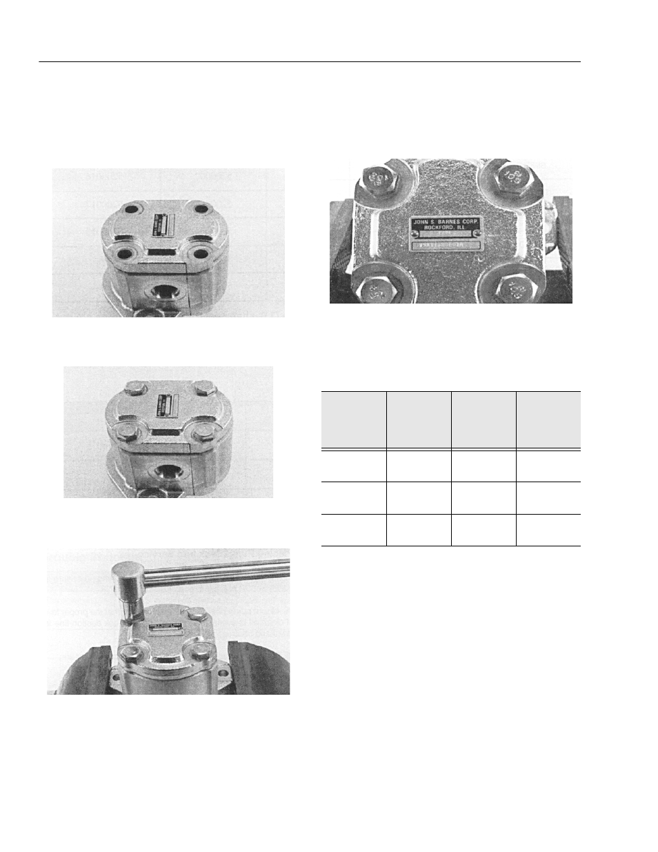
14.
The surface of the rear bearing block should be
slightly below the face of the gear housing. If the
bearing block sits higher then the rear face of the
gear housing then the E-seal or o-ring have shifted
out of the groove. If this is the case, remove the gear
housing and check for proper seal installation.
15.
Install the two remaining dowel pins in the rear of the
gear housing, if applicable, and place the end cover
over the back of the pump.
16.
Install the four spacers, if applicable, and hex head
bolts through the bolt holes in the end cover, hand
tighten.
17.
Place mounting flange of the pump back in the pro-
tected jawed vise and alternately torque the bolts to
the torque specifications in the torque chart. All
torque figures are for "dry torque” bolts.
18.
Remove pump from vise.
19.
Place a small amount of clean oil in the inlet of the
pump and rotate the drive shaft away from the inlet
one revolution. If the drive shaft binds, disassemble
the pump and check for assembly problems, then
reassemble the pump.
20.
The name plate located on the end cover contains
the build date code and the model number. Please
refer to this information when corresponding with
the J.S. Barnes Service Department.
Table 2-3.Hydraulic Pump Bolt Torque Chart
Pump Series
Thread Size
Torque
Values, Black
Oxide End
Cover
Torque
Values, Zinc
Plated End
Cover
W-600
M 8 x 1.25
18-21 ft.lb.
24-30 Nm
16-18 ft.lb.
21.7-24.4 Nm
W-900
M 10 x 1.5
50-55 ft.lb.
68-75 Nm
38-43 ft.lb.
51.5-58.3 Nm
W-1500
M 12 x 1.75
80-85 ft.lb.
108-115 Nm
68-73 ft.lb.
92.2-99 Nm