3 free wheeling option, Engage drive motors & brakes (normal operation), 4 drive motor – JLG 660SJ Service Manual User Manual
Page 61: Description, Free wheeling option -17, Drive motor -17, Description -17, Disengaging drive hubs -17, Drive motor cross section -17, 4 drive motor description
SECTION 3 - CHASSIS & TURNTABLE
3121298
– JLG Lift –
3-17
3.3
FREE WHEELING OPTION
Disengage Drive Motors & Brakes for Towing, etc.
(Free Wheel)
1.
Chock wheels securely if not on flat level surface.
2.
Disconnect both drive hubs by inverting disconnect
caps in center of hubs.
3.
If equipped, move steer/tow selector valve to float (tow)
position by pulling valve knob out.
Engage Drive Motors & Brakes (Normal Operation)
1.
If equipped, move steer/tow valve to steer position by
pushing valve knob in.
2.
Connect both drive hubs by inverting disconnect cap in
center of hub.
3.
Remove chocks from wheels as required.
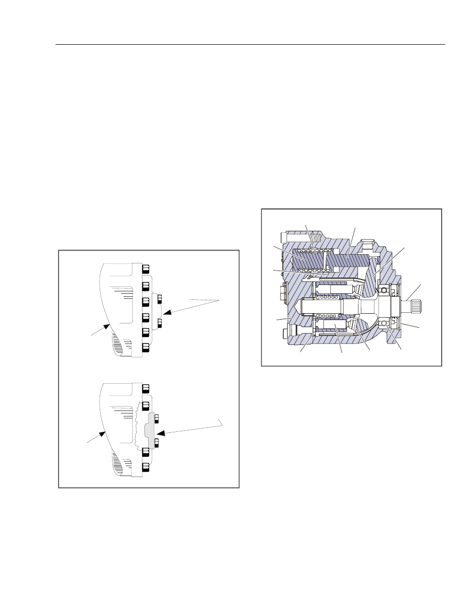
Figure 3-20. Disengaging Drive Hubs
3.4
DRIVE MOTOR
Description
Drive motors are low to medium power, two-position axial pis-
ton motors incorporating an integral servo piston. They are
designed for operation in open and closed circuit applications.
The standard control is a direct acting single line hydraulic
control. The integral servo piston controls motor displace-
ment.
Motors are spring biased to maximum displacement and
hydraulically shifted to minimum displacement. Minimum and
maximum displacement can be set with fixed internal stops.
The large diameter servo piston allows smooth acceleration
and deceleration with relatively large circuit orificing.
Figure 3-21. Drive Motor Cross Section
DISCONNECT
CAP
DISCONNECT CAP
(REVERSED)
DRIVE
HUB
DRIVE
HUB
Drive Hub Engaged
Drive Hub Disengaged
1.
Bias Spring
2.
Servo Piston
3.
Swashplate
4.
Output Shaft
5.
Shaft Seal
6.
Bearing
7.
Slipper
8.
Piston
9.
Valve Plate
10. End Cap
11. Cylinder Block
12. Minimum Angle Stop
1
2
3
4
5
6
7
8
9
10
11
12