6 help menu & fault codes, Table 1-1. lss fault codes, Help menu & fault codes -4 – JLG LSS Boom User Manual
Page 14: Lss fault codes -4
SECTION 1 - OPERATION
1-4
– JLG Lift –
3124287
1.6 HELP MENU & FAULT CODES
The Help Menu is a troubleshooting tool to communicate
detected System Faults to the technician. The following
table documents the Faults for the Load Sensing System.
To access the Help Menu, use the LEFT and RIGHT arrow
keys to select HELP: PRESS ENTER from the Top Level
Menu. Press the ENTER key to view the menu.
When accessing the Help Menu, the JLG Analyzer will dis-
play EVERYTHING OK if the platform is not overloaded
and no difficulties are detected. Otherwise, the JLG Ana-
lyzer will display OVERLOADED.
In the event of difficulty, the user can press ENTER again
to display Logged Help, which is a record of the last 16
Fault Messages. The following table lists each Help/
Logged Message, the Flash Code (for each Fault, the
module will flash the two-digit code on its LED) triggered
by the Fault, and a Description of the Situation (cause).
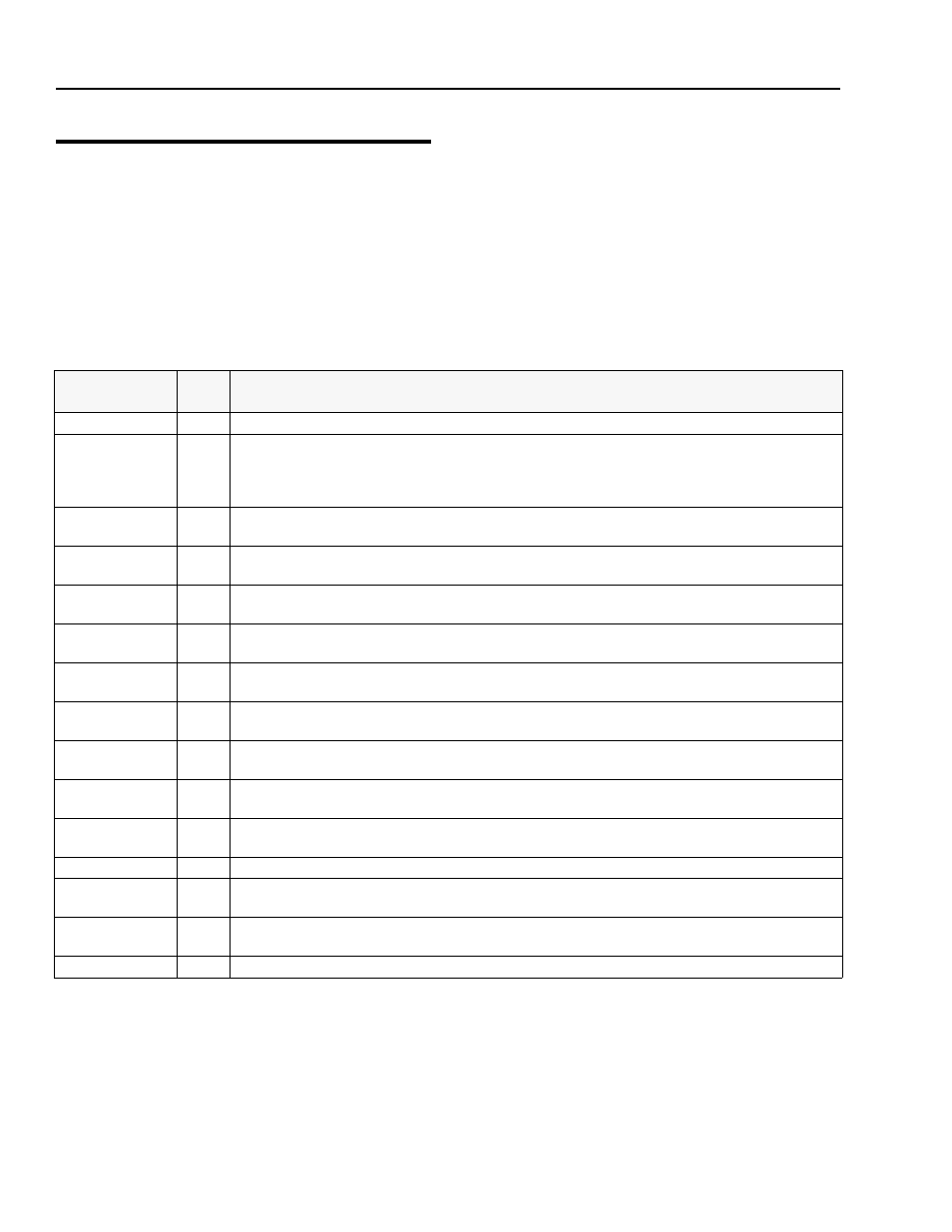
Table 1-1. LSS Fault Codes
Help/Logged
Message
Flash
Code
Description of Situation
Everything OK
LED ON The "Normal" Help Message
Calibration attempt Unsuccessful, Empty Platform appears to weigh too little. Improper Model Selection (Machine Setup) >MAX CAL Calibration attempt Unsuccessful, Empty Platform appears to weigh too much. This situation has the same root causes as BATT TOO LOW 4/1 Incoming Supply Voltage <9.0 Vdc. The control system’s battery voltage is too low due to excessive electrical load or dis- BATT TOO HIGH 4/4 Incoming Supply Voltage >34.0 Vdc. The control system’s battery voltage is too high. This may be due to over-charging or CELL #1 ERROR 8/1 Cell #1’s Bridge <2V, >3V, or could not read Cell #1’s Internal Memory. This situation indicates damage to the sensor or its CELL #2 ERROR 8/2 Cell #2’s Bridge <2V, >3V, or could not read Cell #2’s Internal Memory. This situation indicates damage to the sensor or its CELL #3 ERROR 8/3 Cell #3’s Bridge <2V, >3V, or could not read Cell #3’s Internal Memory. This situation indicates damage to the sensor or its CELL #4 ERROR 8/4 Cell #4’s Bridge <2V, >3V, or could not read Cell #4’s Internal Memory. This situation indicates damage to the sensor or its WATCHDOG RST 9/1 Microprocessor’s Watchdog Timer Triggered. This is an indication that the LSS Module has been exposed to excessive EEPROM ERROR 9/2 Memory used to retain Personality/Machine Setup/Calibration has been corrupted and must be reset by verifying all entries NO CAL 9/3 Calibration has not been successfully completed. A new LSS Module will display this message until properly calibrated. INTERNAL ERR 9/9 Pin excitation <4.25 V. The sensors may be excessively loading the excitation supply, or the LSS Module may have hard- High Side Driver Error. The load attached to OUT1 or OUT2 is shorted to battery or ground and has been detected by the LSS DRDY Interrupt from A/D missing. This may indicate an LSS Module hardware difficulty.
may cause the LSS Module to expect the wrong Empty Platform Weight. This also may be caused by a damaged sensor or
associated wiring. Finally, this condition may occur if mechanical interference between the platform and support structure
exists (all weight must transfer through sensors).
the "
charge.
improper charger operation.
wiring.
wiring.
wiring.
wiring.
electrical noise, or has experienced a hardware difficulty.
and re-calibrating.
ware difficulty.
module.