Interface and outputs – IKA KS 130 control User Manual
Page 30
Control error codes:
ATTENTION! If an error code is encountered, an audio warning
signal is generated and the red Off signal light goes on in the dis-
play field. First, please try to continue operating by turning the
device off and back on again. If it is still not possible to elimina-
te an errorafter an extended wait, please contact our service
department. If you do so, you should always tell us what error
code has been encountered. This simplifies the process of
tracking down the error and makes it possible to form a prelimi-
nary opinion.
Error code
Error
Cause of the error
Er 2
No communication bet- -Interface not connected
ween PC and control de- -PC is not sending any
vice in remote operation data within the amount
with active watchdog func- of time set by the watch-
tion in Mode 1
dog
Er 3
Internal device tempe-
-Permissible ambient
rature too high
temperature exceeded
Er 4
Motor locked or over-
-Agitator table is being
loaded, Problem with
hindered in its stroke motion
read fork signal
-Internal device error
Er 9
Error while reading
-BLP Logik
stored values.
Er 41
Triac defective
-Internal device error
Er 42
Safety relay defective
-Internal device error
WD
No communication bet- -Interface not connected
ween PC and contol de- -PC is not sending any
vice in remote operation data within the amount
with active watchdog func- of time set by the watch-
tion in Mode 1
dog
30
032007
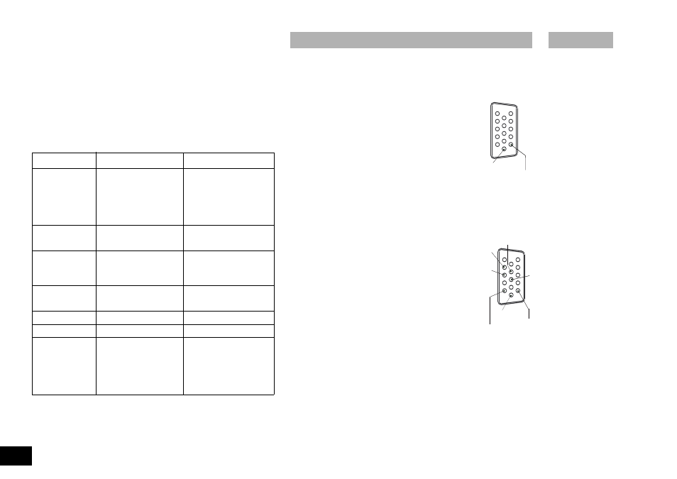
(KS 130 control version only)
The KS 130 control is equipped with a 15-pin SUB-D connector on the rear
side of the device. The pins are assigned in operatin with analog and seri-
al signals.
Analog autput
Voltage values for the speed measurement quantify
are present on the analog pins.
(10)
Analog GND
(15)
Speed measurement value 1VDC / 1000 rpm
RS 232 C serial interface
The serial assignment of the socket can be used to control the device
externally by means of a PC and a suitable application program.
Configuration of the serial RS 232 C interface
• The function of the interface line between the laboratory device and the
automation system is a selection of the signals specified in
EIA Standard RS 232 C, corresponding to DIN 66020 Part
1. For the assignment of the signals, please refer to the illu-
stration.
• Standard RS 232 C applies to the elctronic properties of
the interfaces and the assignment of signal states in accor-
dance with DIN 66259 Part1.
• Transmission procedure: Asynchronous character
transmission in start-stop
mode
• Type of transmission:
full duplex
• Character format:
Character creation according to the data format
in DIN 66022 for start-stop mode. 1start bit;
7character bits; 1parity bit (even); 1stopbit.
• Transmission speed:
9600 baud
• Data flow conrol:
RTS/CTS hardware handshake
• RTS:
(Pin 7) LOW (positive tension)
/ PC may send
• RTS:
(Pin 7) HIGH (negative tension)
/ PC may not send
Interface and outputs
5
1
0
1
5
1
6
1
1
Analog GND
1V = 1000 1/min
5
1
0
1
5
1
6
1
1
Analog GND
RS232_GND
TxD
RxD
RTS
CTS
1V = 1000 1/min