IKA EUROSTAR 20 high speed control User Manual
Page 15
15
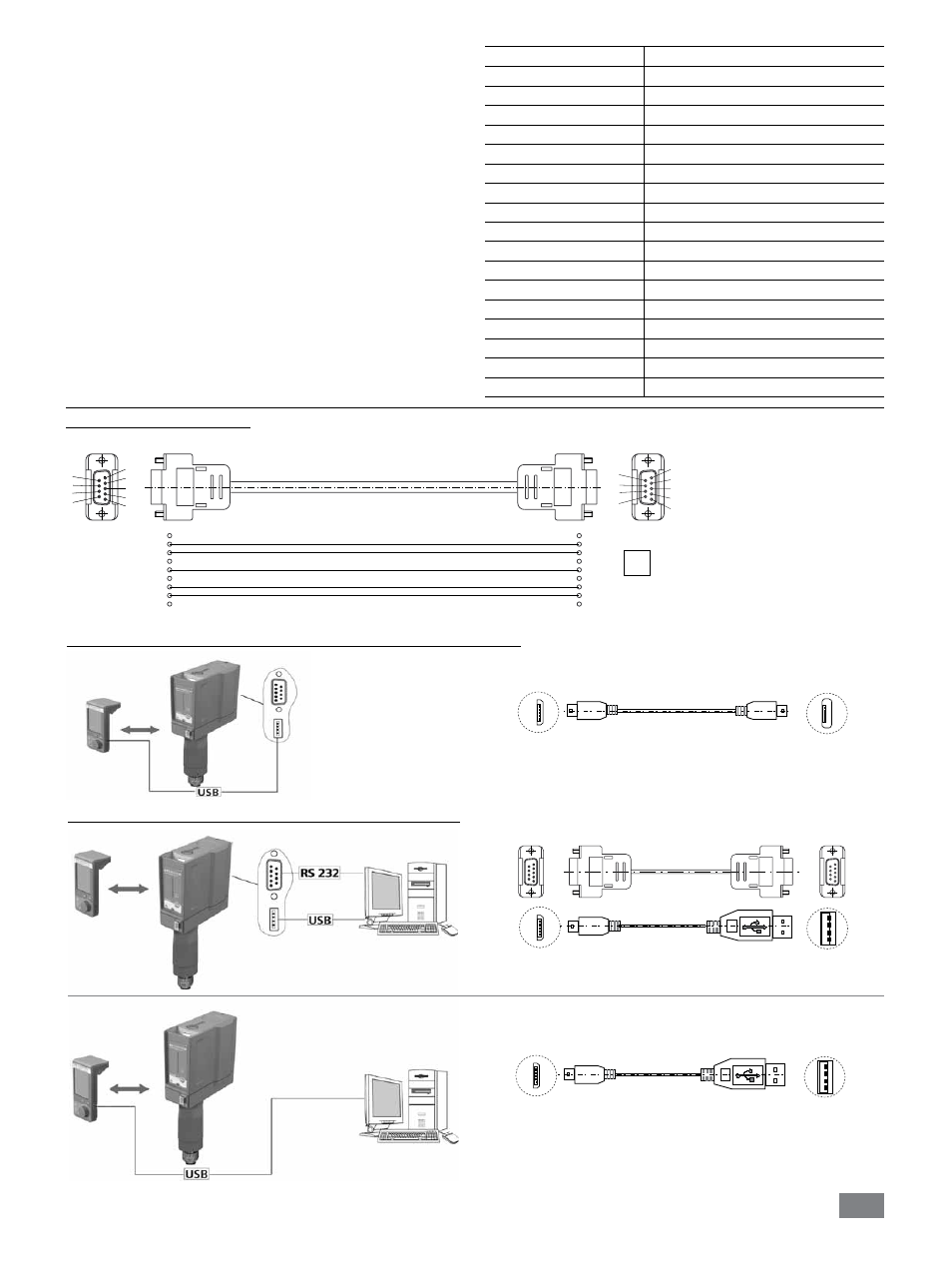
micro B
micro A
USB micro B
USB micro A
Connection capability: Wireless Controller to the EUROSTAR station:
Connection capability: EUROSTAR station to the computer:
A
USB micro B
USB A
9-pin RS 232
9-pin RS 232
or
micro B
A
USB micro B
USB A
micro B
USB A
USB A
- Each individual command (incl. parameters and data) and each re-
sponse are terminated with Blank CR LF (Code: hex 0x20 hex 0x0d
hex 0x20 hex 0x0A) and have a maximum length of 80 characters.
- The decimal separator in a number is a dot (Code: hex 0x2E).
The above details correspond as far as possible to the recommenda-
tions of the NAMUR working party (NAMUR recommendations for
the design of electrical plug connections for analogue and digital
signal transmission on individual items of laboratory control equip-
ment, rev. 1.1).
The NAMUR commands and the additional specific IKA
®
co mmands
serve only as low level commands for communication between the
stirrer machine and the PC. With a suitable terminal or communica-
tions programme these commands can be transmitted directly to the
stirrer equipment. The IKA
®
software package, labworldsoft
®
, pro-
vides a convenient tool for controlling stirring equipment and collect-
ing data under MS Windows, and includes graphical entry features,
for motor speed ramps for example.
The following table summarises the (NAMUR) commands under-
stood by the IKA
®
control equipment.
Commands
Function
IN_NAME
Read device name
IN_PV_3
Read PT1000 value
IN_PV_4
Read current speed value
IN_PV_5
Read current torque value
IN_SP_4
Read rated speed value
IN_SP_5
Read the torque limit value
IN_SP_6
Read the speed limit value
IN_SP_8
Read the safety speed value
OUT_SP_4
Adjust the rated speed value
OUT_SP_5
Adjust the torque limit value
OUT_SP_6
Adjust the speed limit value
OUT_SP_8
Adjust the safety speed value
START_4
Start the motor
STOP_4
Stop the motor
RESET
Switch to normal operating mode
OUT_MODE_n (n= 1 or 2) Change the direction of rotation
IN_MODE
Read the direction of rotation
PC 1.1 Cable (Station to PC)
Required for connecting the 9-pin socket to a PC.
1
2 RxD
3 TxD
4
5 GND
6
7 RTS
8 CTS
9
1
RxD 2
TxD 3
4
GND 5
6
RTS 7
CTS 8
9
PC
1
2
3
4
5
6
7
8
9
9
8
7
6
5
4
3
2
1