Caution – Snorkel S1930-snAP05168 User Manual
Page 37
Chapter 9 – Operation
S1930 – 0361527
33
Note
Holding the steer switch down too long may result in a
sharp turn. This is especially true when driving and steer-
ing at the same time. It may be easier to turn the wheels
in small increments using a series of quick taps on the
steer switch.
2. Set the steer wheels straight ahead after completing
a turn. The steering wheels are not self-centering.
Platform
Use care when entering and exiting the platform to avoid
slipping and/or falling. Securely close the safety chain or
optional swinging gate when the platform is occupied.
Raising and Lowering
The raise speed is proportional to the joystick position.
The farther the joystick is moved, the faster the platform
raises. There is only one lowering speed.
1. Place the drive/lift selector switch (refer to Figure 9.2)
in the lift position.
2. Squeeze and hold the interlock switch against the
joystick.
• To raise the platform, slowly pull the joystick back
until the desired speed is reached.
• To lower the platform, push the joystick forward.
Extending
The platform can be extended and securely locked into
position. Use the following procedure to extend or retract
the platform.
A
Caution
The extension deck is free to move when the pin is
removed. Personal injury may result from extend-
ing the platform deck while the aerial platform is
on a slope. Do not attempt to extend or retract the
platform unless the aerial platform is on a level sur-
face.
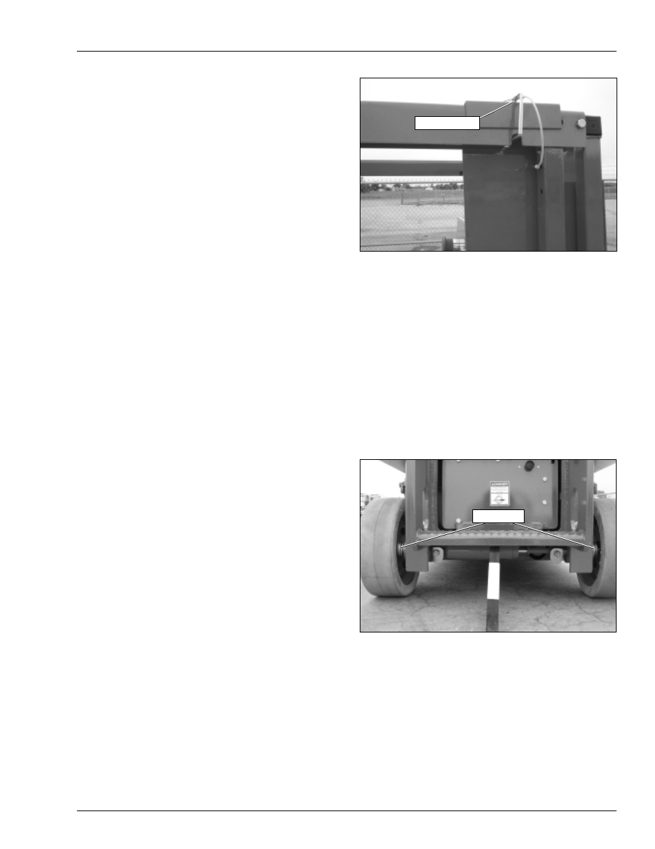
1. Remove the pin from the top rail on the right side of
the platform (refer to Figure 9.3).
2. Stand on the main deck of the platform, facing the
front of the platform. Grasping the top rail of the ex-
tension deck, push forward to extend the deck.
Figure 9.3 – Platform
3. Replace the pin when the platform is extended to
lock it in place.
4. Try to move the rails back and forth to make sure the
platform extension deck is locked in position.
Brakes
Each rear wheel is equipped with a mechanical spring-
applied, hydraulically released parking brake. When the
drive control is in neutral, a spring-activated pin (refer to
Figure 9.4) protrudes through an opening in the brake
disc to prevent movement. A flow control valve slows the
pin movement to allow the aerial platform to stop before
the parking brakes engage.
Figure 9.4 – Rear of Chassis
This system operates automatically to stop and hold the
aerial platform when the drive control is released or power
is interrupted. Manually disengage the brakes before tow-
ing or winching the aerial platform as described under
Towing in Chapter 11 – Emergency Operation.
Swing-Out Trays
Batteries and hydraulic components are enclosed in
swing-out trays (refer to Figure 9.5) on each side of the
chassis.
Extension Pin
Brake Pins