4figure 4 : ourtrigger control box, Figure 2 : upper control box, Figure 3 : lower control box – Snorkel TL49-sn1001+ User Manual
Page 4
4
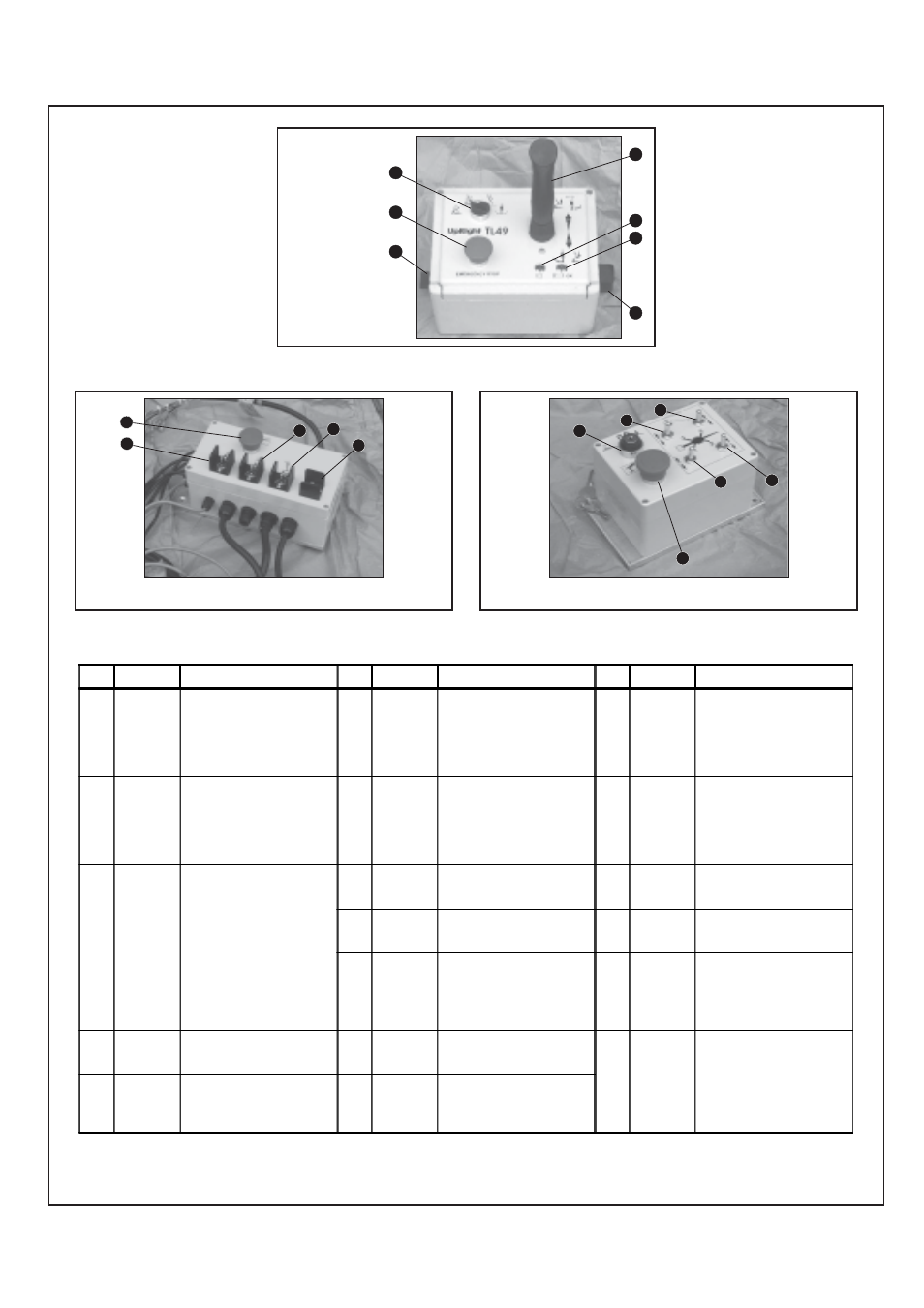
Figure 4 : Ourtrigger Control Box
14
13
16
To operate the Toggle Switches above the Keyswitch (13)
must be turned to the anticlockwise position - CHASSIS.
NOTES :
*
An alarm is located in the Upper Control Box. This will sound when Tilt Sensor is activated, and while this alarm is on only
the Emergency Override controls can be used. This alarm will also sound when an Outrigger Limit Switch opens.
Figure 2 : Upper Control Box
The On/Off/
Emergency
Override Switch
is located on the
left side of the
Upper Control
Box.
To utilize the
Emergency
Override feature
turn and hold
the Switch to the
‘EMERGENCY’
position.
1
2
3
Figure 3 : Lower Control Box
10
8
9
To operate the Toggle Switches above the Keyswitch (13)
must be turned to the anticlockwise position - CHASSIS.
4
6
5
7
11
12
15
17
18
INDEX
NO.
NAME
FUNCTION
INDEX
NO.
NAME
FUNCTION
INDEX
NO.
NAME
FUNCTION
1
SWITCH :
ON/OFF/
EMERGENCY
OVERRIDE
Turn clockwise for power 'ON', in
centre position for power 'OFF' and
anticlockwise for 'EMERGENCY
OVERRIDE'. (Must be held against
spring pressure in this position)
6
BATTERY
CONDITION
INDICATOR
This red L.E.D. (Light Emitting Diode)
indicates the condition of the
batteries. It is constantly illuminated
when the batteries are more than
80% discharged. It flashes repeatedly
when the batteries are 70%
discharged. It is not illuminated when
the batteries are fully charged.
13
KEYSWITCH
Turn the Key anticlockwise to select
the CHASSIS controls or clockwise to
select the PLATFORM controls.
Power OFF is in the centre position.
2
SELECTOR
SWITCH
Select function to be operated. Left
Hand position for BOOM1, the next
position for BOOM2 and the next
position for TELESCOPE. The SLEW
function is the Right Hand position.
Only one function can be selected at
any one time.
7
LEVEL
SWITCH
This toggle switch allows the Platform
to have its 'level' adjusted either
forwards or backwards. To activate
this switch the Platform must be
stowed and the ON/OFF/
EMERGENCY OVERRIDE Switch
must be held to the Emergency
Override Position.
14
EMERGENCY
STOP
SWITCH
Push red button to cut off power to all
functions (OFF). Turn clockwise to
release and restore power.
3
JOYSTICK
CONTROL
LEVER
Squeeze the Interlock Switch,
coloured red. This will activate the
controller. To activate the BOOM1 UP,
BOOM2 UP, TELESCOPE
8
EMERGENCY
STOP
SWITCH
Push red button to cut off power to all
functions (OFF). Turn clockwise to
release and restore power.
15
OUTRIGGER
TOGGLE
SWITCH
Rear Left
The Outrigger assembly can be
extended by holding toggle switch
DOWN, and retracted by holding
switch UP.
RETRACT or ROTATE RIGHT
functions the controller should be
pushed forward.
To activate the BOOM1 DOWN,
9
BOOM 1
TOGGLE
SWITCH
Boom1 can be raised by holding
toggle switch UP, and it can be
lowered by holding toggle switch
DOWN.
16
OUTRIGGER
TOGGLE
SWITCH
Rear Right
The Outrigger assembly can be
extended by holding toggle switch
DOWN, and retracted by holding
switch UP.
BOOM2 DOWN, TELESCOPE
EXTEND or ROTATE LEFT functions
the controller should be
pulled back. The speed that each
function operates is related to how far
the Joystick is moved from the centre
position.
10
BOOM 2
TOGGLE
SWITCH
Boom2 can be raised by holding
toggle switch UP, and it can be
lowered by holding toggle switch
DOWN.
17
OUTRIGGER
TOGGLE
SWITCH
Front Left
The Outrigger assembly can be
extended by holding toggle switch
DOWN, and retracted by holding
switch UP.
4
EMERGENCY
STOP
SWITCH
Push red button to cut off power to all
functions (OFF). Turn clockwise to
release and restore power.
11
TELESCOPE
TOGGLE
SWITCH
The Telescopic Boom can be
extended by holding toggle switch UP,
and it can be retracted by holding
toggle switch DOWN.
18
OUTRIGGER
TOGGLE
SWITCH
Front Right
The Outrigger assembly can be
extended by holding toggle switch
DOWN, and retracted by holding
switch UP.
5
SYSTEM OK
INDICATOR
Illuminates to indicate that the
Outrigger Switches are activated, i.e.
the Outriggers have been properly
deployed and that power is now
available to the Upper Control Box.
12
SLEW
TOGGLE
SWITCH
The elevating assembly can be
slewed LEFT by holding toggle switch
LEFT, and
RIGHT by holding switch RIGHT.