Lukas P 640 TG User Manual
Page 25
25
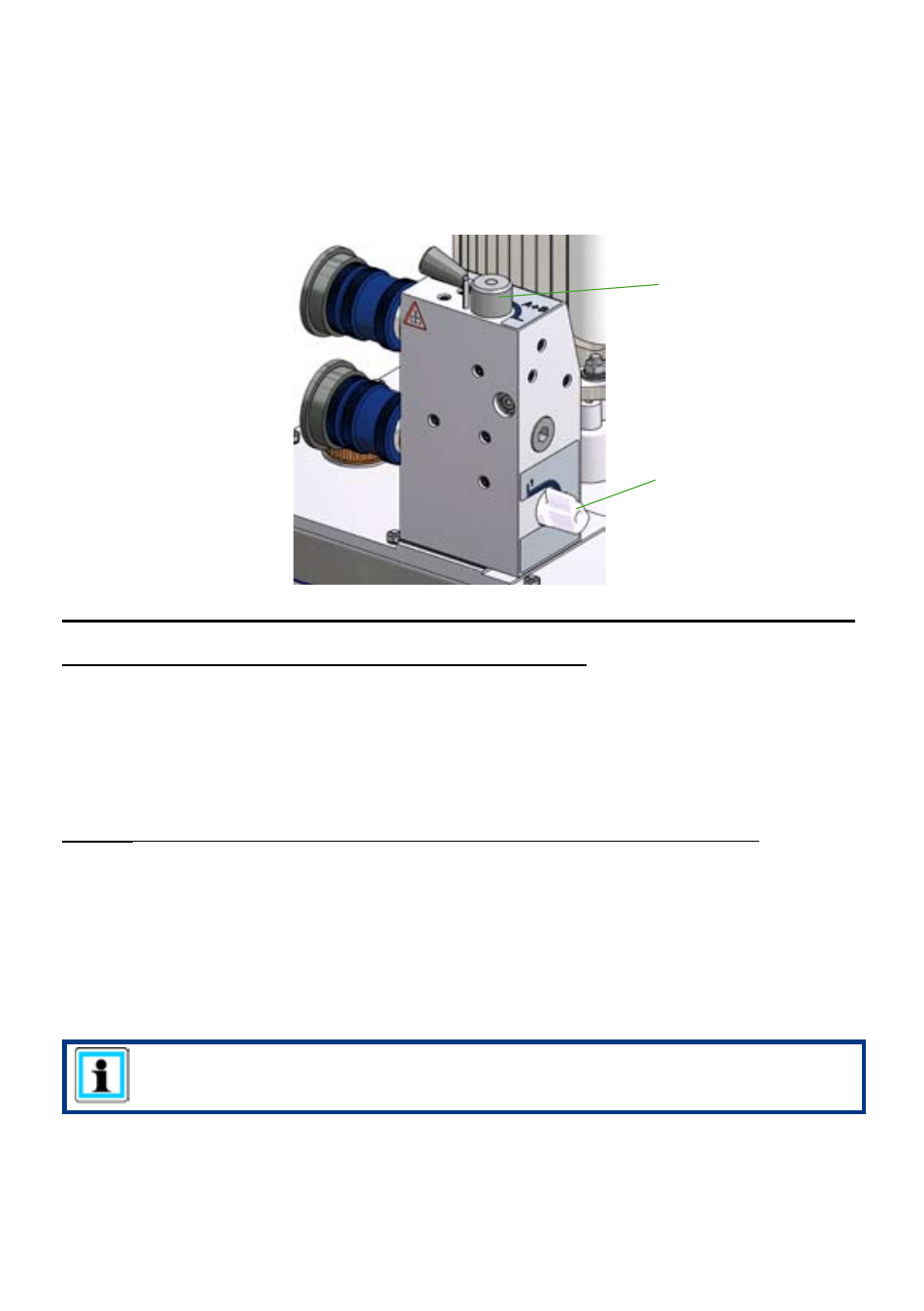
9.3.3 Control valve "automatic operation (ISV valve)"
There is no direct control option for this valve, since the pressure application is controlled
automatically. Nonetheless, the unit also has 2 levers or switches. The top lever controls
whether or not one device (switching position "A") or two devices (switching position “A + B”)
should be operated. The side switch is to control the outlet valve, which means that in switch
position "0" the unit is switched to circulation at static pressure.
Control lever for
switch positions
Control switch / lever
for the outlet valve
Special feature for the operation of control valves "automatic operation (ISV valve)":
Case 1: Two hose pairs and two rescue devices connected:
As a rule, two hose pairs are connected to the valve. Changeover between the two connected
rescue devices is automatic.
Switch the control lever for switch positions to position "A+B".
To supply the connected rescue equipment with hydraulic fluid, the control lever for the outlet
valve must be switched to position "1". To return the valve to circulation at static pressure,
the control lever for the outlet valve must be switched to position "0".
Case 2: One hose pair and one rescue device are connected (at connection A):
If only one hose pair is connected at the valve, the following instructions are important:
1. The valve connections where no hoses are connected, must be sealed by means of
special locking screws, for example, in such a way that no hydraulic fluid can escape on
pressure application.
2. The control lever for switch positions must be in position "A".
3. The hydraulic fluid supply of the connected rescue equipment and switching to circulation
at static pressure take place by switching the control lever for the outlet valve. ("1" = fluid
supply; "0" = circulation at static pressure)
REMARK:
Single-device operation is only possible at connection A.