3 controlling the valves – Lukas P 640 TG User Manual
Page 24
24
9.3 Controlling the valves
Flow chart for stopping Honda motors, unit type 620:
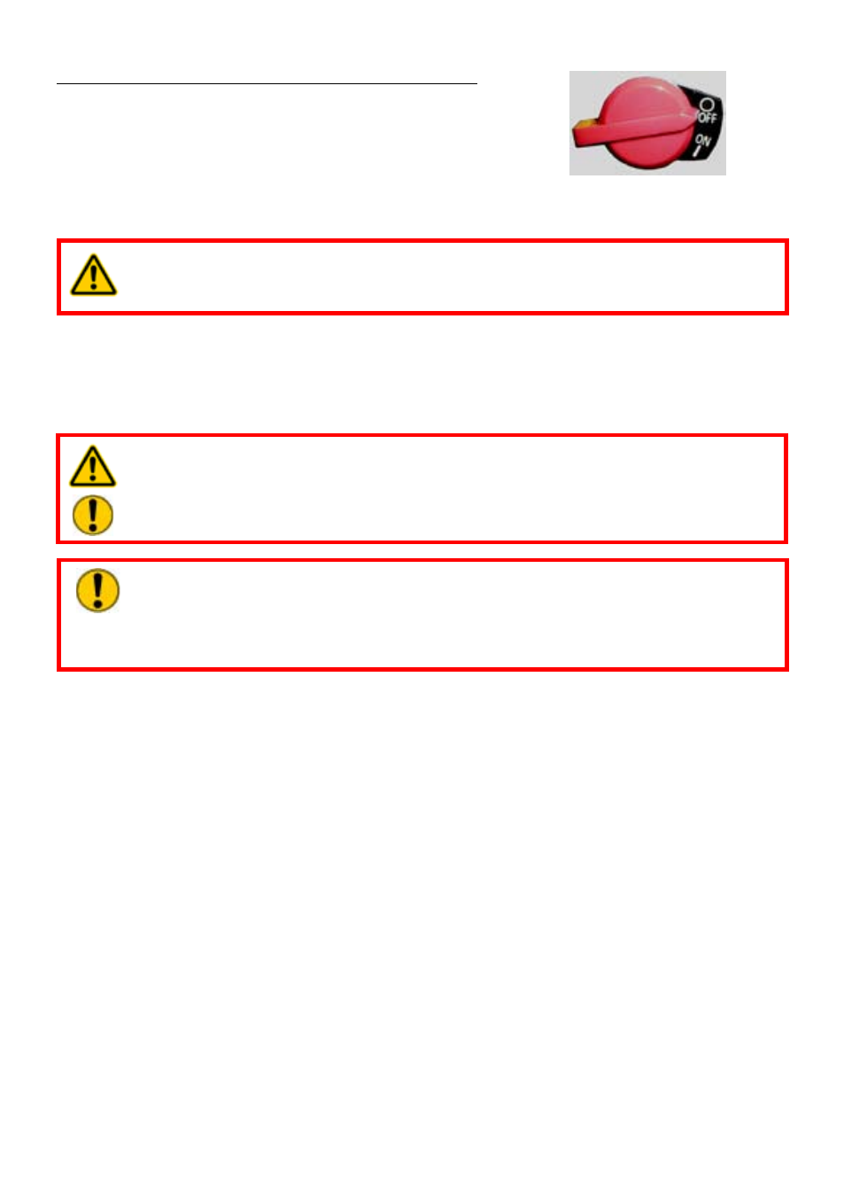
1. Set the ON / OFF switch to the OFF position.
2. When the engine has come to a standstill, close the
fuel tap.
Please consult the separate operating instructions of the motor manufacturer for the precise
procedure for stopping combustion engines!
WARNING / CAUTION!
Never touch the hot motor / engine parts: this could result in severe burns!
9.2.2 Electric motors
The movements of the electric motors are stopped by changing the ON/OFF switch to the
OFF position. This also stops the pumping output of the connected hydraulic pump.
WARNING / DANGER / CAUTION!
For valves which can be connected to several rescue devices, you must ensure
all
unnecessary connections are closed with steel fasteners (supplied with the
valve blocks).
9.3.1 Control valve "single operation"
A lever is fitted on this valve. The pressure application of the pressure hose is controlled by
turning a lever.
There are 2 switching stages:
0 = circulation at static pressure (no pressure supplied to the hydraulic hose)
1 = pressure supply to the pressure hose
9.3.2 Control valve "alternative operation"
A lever is fitted on this valve. The pressure application of the pressure hoses is controlled
by turning a lever.
There are 3 switching stages:
A = pressure supply to the pressure hose 1
B = pressure supply to the pressure hose 2
C = pressure relief of both pressure hoses 1 and 2
CAUTION!
As a general principle,
before starting up the motor, the hydraulic unit is to
be switched to
circulation at static pressure (i.e. the outlet valves are to be
opened, for example). Only in this way is it possible to start the unit without a
hydraulic load.