Lower unit assembly – MBW R422 User Manual
Page 13
- 10 -
Shoe and Spring box Guard Removal
1.
Remove the four socket head cap screws (#23) and
lock washers (#24) that secure the shoe (#12) to the
lower unit assembly and remove the shoe.
2.
Lift the spring box guard (#13) off the spring box
assembly.
3.
Remove the o-ring (#10) from the spring box guard
(#12).
Spring box Disassembly
WARNING
Working with compressed springs! Failure to
follow the next set of steps very carefully could
result in injury or death.
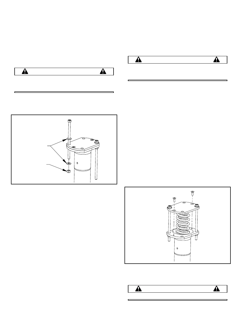
1.
Flip the spring box assembly upside down.
2.
Insert the spring box tool (MBW #20260) rods into the
spring box assembly as shown in Figure 3.
3.
Make sure the rods are 180° apart.
4.
Place the washers over the rods and run the nuts
down so the washers are snug against the cover (#8).
5.
Remove the flat head socket screws (#20) holding
the cover to the spring box.
6.
While holding the hex nuts from turning, slowly and
evenly back off the rods on the cover side of the
spring box.
7.
After the tension is removed from the cover, the
spring box tools and the cover can be removed. See
Figure 4.
8.
Remove the o-ring (#1) from the cover.
9.
The lower springs (#6 & #7) can be removed from the
spring box (#14).
10. Place a drift pin or 5/8” dia. steel rod into the
connecting pin hole in the ram head (#15). Use this to
hold the ram head from turning while removing the
nylon lock nut (#25) & bushing (#2). Remove and
discard nylon lock nut.
11. Remove the spring separator (#16) and slide bearing
(#17).
12. Remove upper springs (#6 & #7) and ram shaft (#15).
13. Remove the retaining ring (#19) and ram shaft slide
bearing (#18) from top of spring box (#14).
Lower Unit Assembly
WARNING
Working with compressed springs! Failure to
follow the next set of steps very carefully could
result in injury or death.
Refer to Lower Unit Assembly, page 16.
1.
Install the ram shaft slide bearing (#18) and retaining
ring (#19) into the top of spring box (#14).
2.
Install ram shaft (#15) into top of spring box.
3.
Turn spring box (#14) up side down and install the
upper springs (#6 & #7).
4.
Wrap slide bearing (#17) around spring separator
(#16) and install into spring box.
5.
Apply high strength (red) thread locker to threads of
new nylon lock nut (#25) and install bushing (#2) and
lock nut (#25) to the ram shaft. Torque to 60 ft lbs (81
N•m).
6.
Insert the lower springs (#6 & #7).
7.
Lightly grease the o-ring groove in the cover (#9) and
install a new o-ring (#1).
8.
Insert the spring box tool (MBW #20260) rods into the
spring box as shown in Figure 4.
9.
Slowly draw the cover down onto the spring box by
alternately tightening each rod.
WARNING
Keep the cover level with the spring box.
FLAT WASHERS
HEX NUT
Figure 3
Figure 4