Behringer Xenyx User Manual
Page 6
6
XENYX 1204/1204FX
+
Please remember that you can only use either the
microphone or the line input of a channel at any
one time. You can never use both simultaneously!
LOW CUT
The mono channels of the mixing consoles have a high-slope
LOW CUT filter for eliminating unwanted, low-frequency signal
components (75 Hz, 18 dB/octave).
TRIM
Use the TRIM control to adjust the input gain. This control
should always be turned fully counterclockwise whenever you
connect or disconnect a signal source to one of the inputs.
2.1.2 Equalizer
All mono input channels include a 3-band equalizer. All bands
provide boost or cut of up to 15 dB. In the central position, the
equalizer is inactive.
The circuitry of the British EQs is based on the technology
used in the best-known top-of-the-line consoles and providing a
warm sound without any unwanted side effects. The result are
extremely musical equalizers which, unlike simple equalizers,
cause no side effects such as phase shifting or bandwidth
limitation, even with extreme gain settings of ±15 dB.
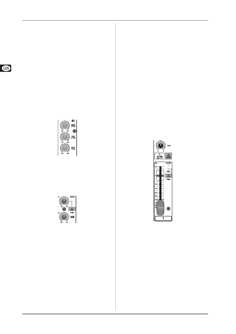
Fig. 2.2: The equalizer of the input channels
The upper (HI) and the lower band (LO) are shelving filters
that increase or decrease all frequencies above or below their
cut-off frequency. The cut-off frequencies of the upper and
lower band are 12 kHz and 80 Hz respectively. The mid band is
configured as a peak filter with a center frequency of 2.5 kHz.
2.1.3 Aux sends
Fig. 2.3: The AUX SEND controls in the channel strips
Aux sends take signals via a control from one or more channels
and sum these signals to a so-called bus. This bus signal is sent
to an aux send connector and then routed, for example, to an
active monitor speaker or an external effects device. The return
from an external effect can then be brought back into the console
via the aux return connectors.
For situations which require effects processing, the aux sends
are usually switched post-fader so that the effects volume in a
channel corresponds to the position of the channel fader. If this
were not the case, the effects signal of the channel would
remain audible even when the fader is turned to zero. When
setting up a monitor mix, the aux sends are generally switched
to pre-fader; i.e. they operate independently of the position of
the channel fader.
Both aux sends are mono, are sourced after the equalizer and
offer up to +15 dB gain.
+
If you press the MUTE/ALT 3-4 switch, aux send 1 is
muted, provided that it is switched post-
fader. However, this does not affect the aux send 2
of the 1204FX.
AUX 1 (MON)
In the 1204FX, aux send 1 can be switched pre-fader and is
thus particularly suitable for setting up monitor mixes. In the
1204, the first aux send is labeled MON and is permanently
switched pre-fader.
PRE
When the PRE switch is pressed, aux send 1 is sourced pre-
fader.
AUX 2 (FX)
The aux send labeled FX is for sending to effects devices and
is thus set up to be post-fader.
In the 1204FX, the FX send is routed directly to the built-in
effects processor.
+
If you wish to use the internal effects processor,
the STEREO AUX RETURN 2 connectors should not
be in use.
+
1204FX: you can also connect an external effects
processor to aux send 2, however the internal
effects module will be muted.
2.1.4 Routing switch, solo and channel fader
Fig. 2.4: Panorama and routing controls
PAN
The PAN control determines the position of the channel signal
within the stereo image. This control features a constant-power
characteristic, which means the signal is always maintained at a
constant level, irrespective of position in the stereo panorama.
MUTE/ALT 3-4
You can use the MUTE/ALT 3-4 switch to divert the channel
from the main mix bus to the Alt 3-4 bus. This mutes the channel
from the main mix.
MUTE-LED
The MUTE LED indicates that the relevant channel is diverted
to the submix (Alt 3-4 bus).
CLIP-LED
The CLIP LED lights up when the input signal is driven too high.
In this case, turn down the TRIM control and, if necessary, check
the setting of the channel EQ.
2. CONTROL ELEMENTS AND CONNECTORS