Temperature indicating system with fuel flow – J.P. Instruments EDM 760 Instrument Installation Manual User Manual
Page 5
Installation manual for the EDM-760 Twin
STC SA00729SE
Report No. 760
Temperature indicating system with Fuel Flow
Date 7/20/99 Rev NC
Page 5 of 19
15) INDICATOR INSTALLATION & RECORD
Locate a 3.125” diameter hole in the instrument panel, where you would like to mount the indicator per drawing 760124.
Mount the indicator in the panel, using the four 6-32 X.0.15" screws. The screws must not penetrate the bezel more than
.120". Three connectors are protruding from the rear of the instrument. Two 25 pin and one 15 pin connector. The top 25-pin
connector connects the left engine harness. The bottom 25-pin connector, connects the right engine harness and the center
15-pin connector, connects the power and options like OAT.
Record the installation of the EDM-760 on a FAA form 337
.
Make entry in the aircraft logbook.
16) DESCRIPTION
GENERAL
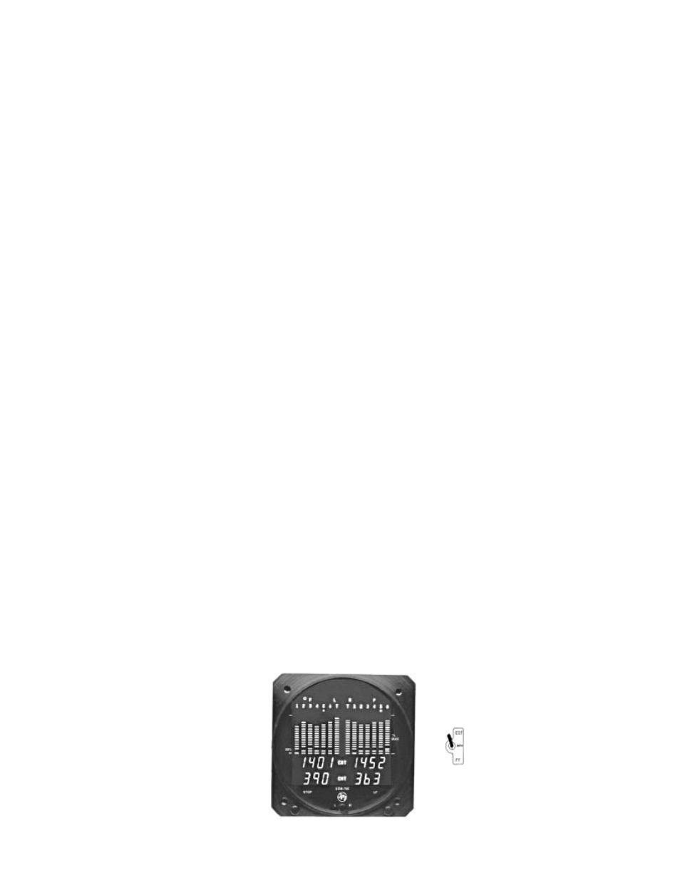
The EDM-760 temperature indicator displays temperature digitally and in analog format. The analog display is an electronic
bar graph of EGT & TIT temperatures presented as a percentage of 1650
o
F. Below the vertical columns the specific value for
EGT and CHT are displayed digitally for both engines. EGT top and CHT bottom. The dot over the column indicates which
cylinder's digital information is presently displayed. The missing bar in the graph represents the CHT trend, showing which
cylinder is hotter or cooler and is checked digitally. Depressing the LF and STEP button simultaneously brings up the Pilot
Programmable Mode in which the scan rate, OAT, and EGT resolution can be adjusted. Exit by Depressing STEP.
If the EDM-760 buttons are not depressed for 1 minutes the system will start scanning automatically. Depressing the STEP
button will stop the automatic scan and index through all the functions available. During cruise, if the LF button is depressed
for five seconds (normalize mode) the bar graph will level at mid scale. The leveled bars represent the peaks of each column.
Each bar represents 10
o
F and now acts as an EGT & TIT trend monitor, quickly showing an increase or decrease in
temperature. Depress again to return too normal; nothing else is affected.
TIT, OAT, OIL, BAT (voltage), Fuel flow functions and CLD (Rate of change of CHT in degrees per minute) are displayed
digitally with headlines after the temperature, such as "230 OIL". A large value of "CLD" indicates shock cooling which has a
detrimental effect on the engine and is usually associated with rapid descents at low power. Probes not installed will not be
displayed.
An alarm causes the digital function to flash when the particular limit is reached. Factory generic set alarm limits for
example: CHT (450
o
F) and OIL (230
o
F) are lower than the actual aircraft limits. The values may be adjusted to individual
aircraft limits by pressing the reset button located on the rear of the instrument. Other factory set alarm limits are: "BAT"
Voltage 15.5/12.0 or 31.0/24.0 Hi/Lo as appropriate; "DIF" (differential Hi/Lo EGT) 500
o
F; "TIT" 1650
o
F Hi; "OIL" Lo 90
o
F;
"CLD" (Rate of change of cylinder head temperature in degrees per minute) -60 degrees/minute. An alert output is available
for the above functions that will sink 250 ma load. The pilot should be aware of the setting of each alarm for his particular
aircraft. All alarms are "Canceled" in two ways: One by tapping the step button which will remove the alarm for 10 minutes.
The second way is by holding the step button in for 5 seconds and seeing the word "OFF". Then, only that particular alarm
is canceled . Canceled alarms will not appear again until the power has been removed and reapplied to the EDM-760. The
entire display dims automatically depending on the ambient lighting.
17)
Alarm limits set for this
instrument if different from
JPI limits.
CHT__________
OIL__________
TIT__________
DIF__________
CLD__________
BAT__________
TECH_________
DATE_________