J.P. Instruments EDM 930 Primary Instructions for Continued Airworthiness User Manual
Page 4
EDM-900/930 Instructions for Continued Airworthiness Rev E
Date 5-24-2014 Page 4 of 6
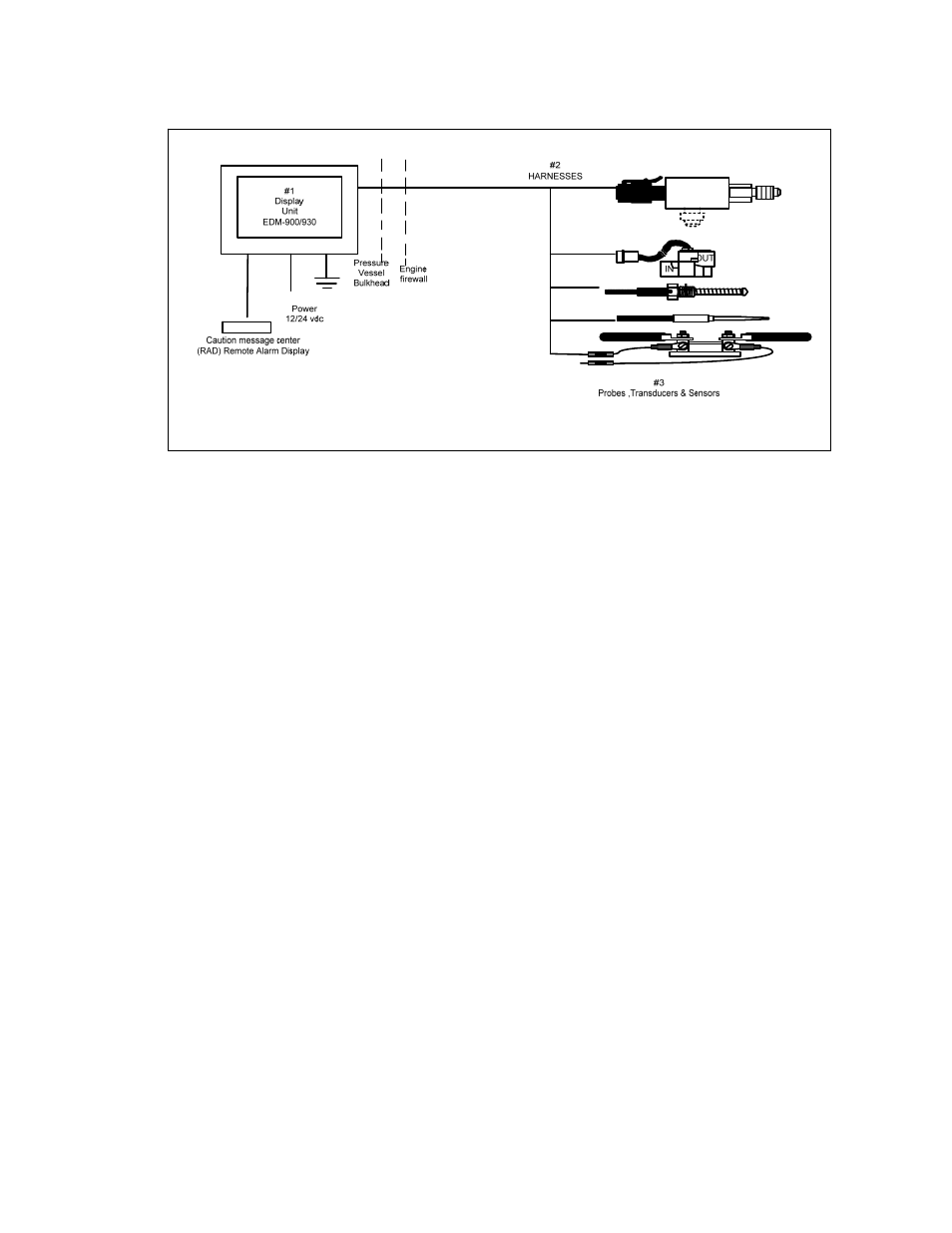
2.1 Display Unit PNs 790000-A and 790000-C
The EDM-900/930 receives, processes and displays the data on a VGA TFT color
display. In addition, the EDM-900/930 receives GPS data. The EDM-900/930 also
transmits fuel flow and fuel level data to a GPS and controls the external Master Caution
Message Center (RAD) Remote Access Display.
2.2 Harnesses
The extension cables route the signals from the probes, transducers and sensors to the Display
unit. These extension cables ar e F AA a p pr o ve d. The installation of these extension
cables are per J.P.Instruments Inc. report 908 installation instructions.
2.3 Probes, Transducers and Sensors
These components are used to measure pressures, temperatures, fuel flow, volts, amps, fuel levels
and many other engine and aircraft system functions. The analog signals produced by the
transducers and probes are routed through the extension cables to the various EDM inputs.
These probes, transducers and sensors are TSO approved and currently are used on other
J.P.Instruments Inc. STC'd, TSO'd products. The installation of these probes, transducers
and sensors are per J.P.Instruments Inc. report 908 installation instructions.
2.4 EDM-900/930 System Parts List
See section 29 page 32 Component Parts List in Report 908 Installation Instructions.
3.0 Applicable Documents
The following documents are listed for reference only.
Each document is applicable only to the extent specified herein.
Report 908 EDM-900/930 Installation Instructions.