Fig. 19, Fig. 18 – L.B. White 170 Dual Fuel User Manual
Page 17
17
1.
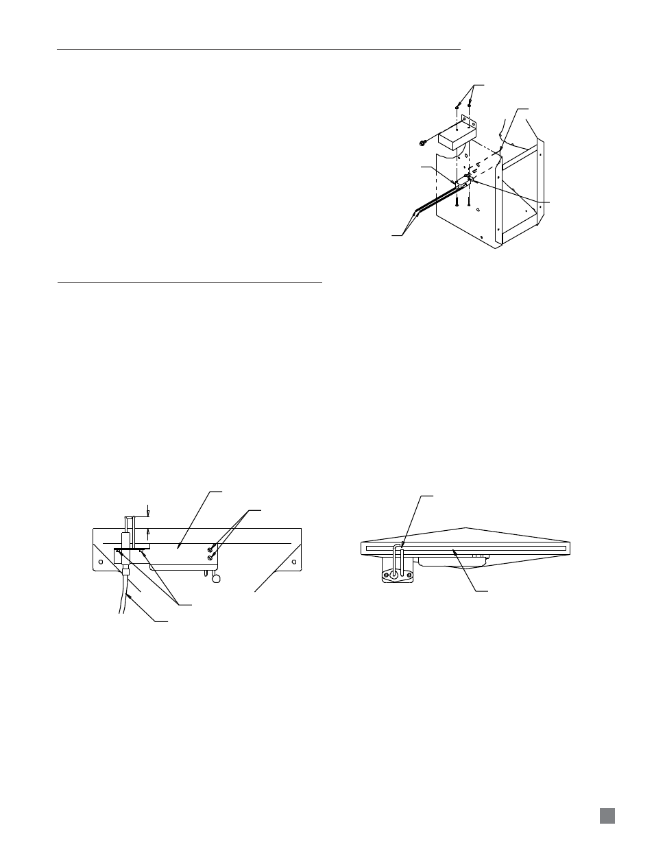
The igniter and sensor assembly is located at the top
of the burner casting. See Fig. 19.
2.
Remove the two screws securing the mounting
bracket to the burner. Remove igniter assembly.
3.
Disconnect high voltage cable from igniter assembly.
4.
Remove the screws that secure the igniter/sensor to
the mounting bracket.
■
The igniter and ground rod should be cleaned to
maintain proper ignition.
-- Use steel wool or emery cloth.
-- Rub briskly to remove buildup of dust, dirt, and oxide.
■
Check the igniter’s base for cracks.
-- Replace the igniter if cracks are found.
5/32 IN. DISTANCE FROM IGNITER
TOP TO BURNER TOP
MOUNTING BRACKET
IGNITER BRACKET
MOUNTING SCREWS
IGNITER/SENSOR MOUNTING SCREWS
HIGH VOLTAGE IGNITION LEAD
ELECTRODE GAP IS 1/8" &
CENTERED OVER BURNER PORT
BURNER PORT
TOP VIEW
FRONT VIEW
FIG. 19
SWITCH W/ PADDLE
LEADS
NUTS
PADDLE
OBLONG HOLE
HOUSING SIDE
PANEL
1.
Remove screws and turn switch assembly so the
switch paddle can be pulled through oblong hole on
side of fan housing. See Fig. 18.
2.
When installing replacement switch, do not bend the
switch arm, otherwise ignition problems may occur.
FIG. 18
AIR PROVING SWITCH
IGNITER AND FLAME SENSOR ASSEMBLY
12.7 mm
3.2 mm &