Service instructions, Motor and fan assembly thermocouple, Burner orifice – L.B. White 100 Tradesman Portable Forced Air User Manual
Page 14: Attention, Fig. 7, Fig. 6, Fig. 8
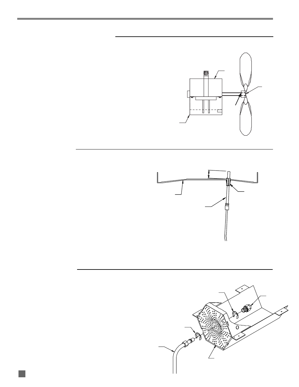
1. Disconnect the thermocouple contact nut from the
pilot safety control valve.
2. Disconnect the two electrical leads from the energy
cut off block on the thermocouple.
3. Pull the thermocouple from its retaining clip.
ATTENTION
■
When properly installed, the tip of the thermocouple will
extend 1/2 in. from the retaining clip on the combustion
side of the burner plate.
■
When tightening the contact nut of the thermocouple,
thread the nut in fingertight and snug it in place a
wrench.
FIG. 7
1. Loosen the set screw on the fan hub and slide the fan
off of the fan shaft.
2. Remove the nut and bolt that secure the motor
within the motor mount.
3. When installing motor and fan:
-- Ensure motor is centered within the motor mount.
-- Set screw of fan must be located over flat of motor
shaft before tightening
-- Position fan so side opposite of fan hub is flush with
end of shaft
-- Spin the fan to make sure it does not hit heater
components.
FIG. 6
Service Instructions
MOTOR AND FAN ASSEMBLY
THERMOCOUPLE
BURNER PLATE
THERMOCOUPLE
CLIP
1/2 INCH
BURNER ORIFICE
RING, FLAT
ORIFICE
BURNER PLATE
RING, BOWED
MANIFOLD
1. Loosen the compression nut at the orifice inlet.
2. Remove the bowed retaining ring nearest the
compression nut.
3. Reach down the heater barrel, and pull the orifice
from the burner plate.
4. The replacement orifice ships with two retaining rings.
Push the flat ring into the slot nearest the orifice
holes. Reaching down the barrel, position the orifice
into the burner plate. Secure the orifice into position
using the bowed retaining clip.
FIG. 8
13
MOTOR CENTERED
IN MOUNT
FRONT OF HUB
FLUSH AT
SHAFT END
MOTOR
HUB
SIDE
OPPOSITE
HUB