Operation, Operation...continued – Steele Products SP-PB125 User Manual
Page 6
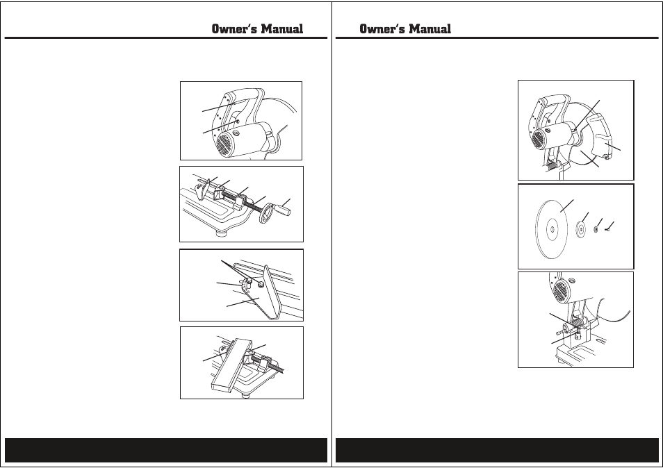
ON/OFF trigger switch (Fig. 4)
To start the cut-off saw, squeeze the trigger
switch (1). To stop the cut-off saw, release the
trigger switch.
Reset switch (Fig. 4)
If the cut-off saw does not start when the trigger
switch is depressed, press the reset switch.(2)
Squeeze the trigger switch to start.
Swivelling vise clamp assembly with
quick-release latch (Fig. 5)
Always secure the workpiece between the angle
plate and the vise pressure plate when cutting.
1.Place the workpiece between the angle
plate (1) and the vise pressure plate (2).
2.Push the vise screw (3) toward the angle
plate and turn the vise wheel (4) clockwise to secure.
To release, turn the wheel counter-clockwise two
turns,raise the quick-release latch (5) and pull the
vise screw towards you.
Angle plate (Fig. 6 and 7)
The angle plate can be moved forward,backward, or
rotated for angle cutting.
1.To set a cutting angle, loosen the two bolts (1) and
rotate the angle plate (3) up to 45˚ right or 45˚ left.
Align the index (2) with the red line on the saw
table. Retighten the bolts.
2.Always centre the workpiece over the table slot-web
to maximize cutting depths.Move the vise pressure
plate (4) toward the angle plate (3).Tighten angle
plate bolts (2)and vise pressure plate (4).
3.To move the angle plate (3), remove the two
bolts (1) and washers. Move the angle plate to
the desired position and align the angle plate
with the threaded holes on the saw base.Insert the
two bolts and washers and tighten to secure the
angle plate to the table.
Fig. 4
Fig. 5
Fig. 6
Fig. 7
1
2
1
2
5
3
4
2
1
3
3
4
Operation
10
Installation and removal of metal cutting disc
(Fig.8 and 9)
1.Unplug the cut-off saw.
2.Push the arbor lock lever (1) towards the metal
cutting disc (2) and slowly turn the disc (either
direction) until the disc locks. (Fig. 8)
3.Push back the lower blade guard (3) and loosen
the hex bolt (6) in the centre of the disc using
the wrench. Remove the bolt (6), washeraq (5),
flange (4) , and disc (2) . (Fig. 9).
4.To install a new metal cutting disc, reverse the
process in step 3. Do not overtighten the bolt.
5.Make sure all guards are in place and the disc
rotates freely.
6.Adjust the depth stop bolt (Fig. 10). Return the
wrench to the storage slot.
7.Plug in the cut-off saw.
8.Run the cut-off saw and check to make sure the
disc is in good condition. Always stand to one
side when turning on the cut-off saw. When
testing a new disc, run the the cut-off saw for
3minutes. When testing an existing disc, run the
cut-off saw for 1minute.
Adjusting the cutting depth (Fig. 10)
The diameter of the metal cutting disc decreases
with use. The depth stop bolt should be adjusted
periodically to prevent the disc from cutting the
work surface below the cut-off saw table.
1.Loosen the lock nut (1).
2.Turn the stop bolt (2) to set the downward travel
of the disc.
3.Lower the saw to check the depth.
4.Repeat steps 2 and 3 until the downward travel
of the disc is at the desired level.
5.Tighten the lock nut (1) to secure the cutting
depth assembly.
Fig. 8
Fig. 9
Fig. 10
2
4
5
6
1
1
2
2
3
Operation...continued
11