Know your cut-off saw, Assembly and adjustments – Steele Products SP-PB125 User Manual
Page 5
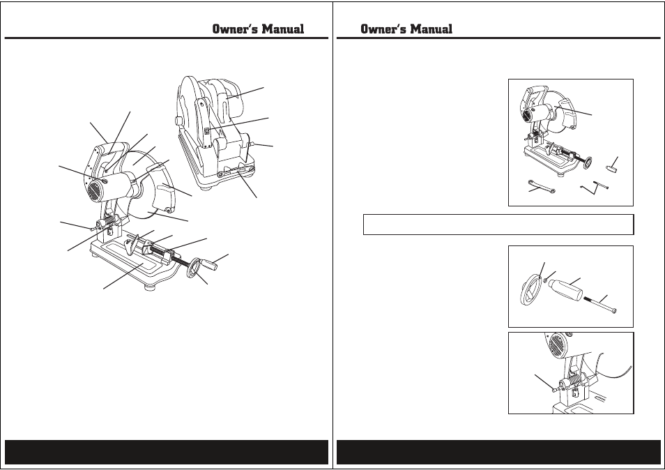
D-handle
A
Trigger switch
B
Reset switch
C
Upper blade guard
D
Arbor lock
E
Lower blade guard
F
14" metal cutting disc
G
Angle plate
H
Vise pressure plate
I
Quick-release latch
J
Vise handle
K
Vise wheel
L
Saw table
M
Depth stop bolt
N
Wheel lock lever
O
Carbon brush cap
P
Carrying handle
Q
Laser switch
R
Wrench
S
A
B
e
F
R
J
H
I
G
K
O
S
M
O
N
P
C
D
E
Q
L
Know your cut-off saw
8
Unpacking (Fig.1)
1.Remove the cut-off saw (1) from the carton
by lifting it by the carrying handle.
2.Place the cut-off saw on a secure surface
and examine it carefully. Ensure that you
have:
• 14" cut-off saw assembly (1)
• Vise clamp handle
(2)
• Threaded bolt and nut
(3)
• Blade wrench
(4)
Although this cut-off saw requires minimal
assembly, it does, however, require adjustments
to operate properly. For your safety, make all
adjustments prior to plugging in the cut-off saw.
Vise clamp assembly (Fig. 2)
1.Insert the bolt (1) through the vise clamp
handle (2).
2.Tighten the nut (3) on the bolt.
3.Insert the assembled handle into the
opening (4) on the vise wheel and turn
handle clockwise to secure to the wheel.
Raise/lower the saw (Fig. 3)
1.Pull out the wheel lock lever (1) and use the
handle to raise or lower the cut-off saw.
2.Push in the wheel lock lever (1) to lock the
cut-off saw in the raised or lowered position.
WARNING:
IF ANY PART IS MISSING OR DAMAGED, DO NOT PLUG IN THE CUT-OFF SAW
UNTIL THE MISSING OR DAMAGED PART IS REPLACED.
Fig. 1
Fig. 2
1
4
2
3
4
3
2
1
Fig. 3
1
Assembly and adjustments
9