Steele Products SP-PB140 User Manual
Page 5
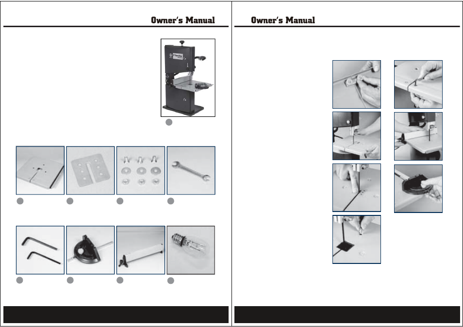
Components
The band saw is supplied with the following components:
1. Band Saw
2. Table
3. Table Insert
4. Recessed hex bolt, washer and nuts (x3)
5. Wrench
6. Hex keys (x2)
7. Miter Gauge
8. Rip Fence
9. Light Bulb
1
6
2
7
3
5
9
4
8
9
Assembly
The band saw is shipped partly disassembled and the work table
and rip fence have to be installed prior to use.
1. Remove the bracket from below
the work table by loosening the
2 knobs. Remove the 2 knobs,
bracket and screws.
2. Place the work table on the table
trunnion by threading the saw
blade through the slot in the
table.
3. I nsert the table insert in the
centre of the table.
4. Align the work table so that the
blade runs through the centre of
the table insert’s slot.
5. Fasten the work table to the table
trunnion using the three recessed
hex bolts, plain washers and
nuts.
Caution:
Make sure the screws are
tightened securely to ensure they
do not loosen in use.
6. Replace the bracket under the
work table using the two screws
and two thumb nuts.
7. Attache the rip fence to the table
and secure it by pushing down
the rip fence locking handle.
Note.
It may be necessary to
rotate the handle anticlockwise
to be able to slide the rip
fence over the table and then
clockwise before locking the
handle in position.
8. Attach the miter gauge onto the
table by sliding it into the miter
gauge slot.
10